Error Codes and Messages Troubleshooting Procedures
Phaser® 6120 Color Laser Printer Service Manual
4-15
Error Codes and Messages Troubleshooting
Procedures
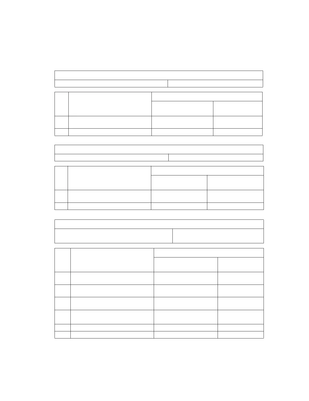
04: Engine Board Malfunction
05: Flash ROM Malfunction
08: Main Motor Malfunction
Note: REM = Motor/Solenoid ON and LOCK = Motor OFF (failure)
Relevant Electrical Parts
PWB-A (Engine Control Board)
Step Action
WIRING DIAGRAM
Control Signal
Location (Electrical
Component)
1 Check the PWB-A connector for proper
connection and correct as necessary.
--
2 Change PWB-A. - -
Relevant Electrical Parts
PWB-A (Engine Control Board)
Step Action
WIRING DIAGRAM
Control Signal
Location (Electrical
Component)
1 Check the PWB-A connector for proper
connection and correct as necessary.
--
2 Change PWB-A. - -
Relevant Electrical Parts
Main Motor (M1) PWB-A (Engine Control Board)
Power Unit (PU)
Step Action
WIRING DIAGRAM
Control Signal
Location (Electrical
Component)
1 Check the M1 connector for proper
connection and correct as necessary.
--
2 Check M1 for proper drive coupling and
correct as necessary.
--
3 Check the PWB-A connector for proper
connection and correct as necessary.
--
4 M1 operation check. PWB-A PJ8A-5 (REM)
PWB-A PJ8A-8 (LOCK)
2-G∼H
5 Change PWB-A. - -
6 Change PU (LVPS). - -

 Loading...


