Disassembly/Assembly Procedures
Phaser® 6120 Color Laser Printer Service Manual
5-14
Power Unit (PU)
1. Remove the PWB-P (Image Processor Board). See PWB-P (Image Processor Board) on
page 5-9.
2. Remove the PWB-A (Engine Control Board). See PWB-A (Engine Control Board) on
page 5-12.
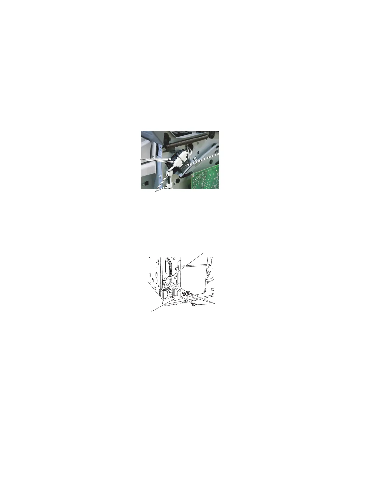
3. Disconnect the rear white and black connectors [2] of the Fusing Safety Switch [1] and
remove the wire from the two wiring saddles [3].
4. Remove three screws [5] from the Power Switch Assy [4] and remove the wire from the
wiring saddle [6].
Note: One of the two Power Switch screws is used to secure the Power Switch Assy to the
High Voltage Unit.
4139fs2021c2
[2]
[1]
[3]
[5]
[6]
[4]
4139fs2074c1

 Loading...


