Disassembly/Assembly Procedures
Phaser® 6120 Color Laser Printer Service Manual
5-23
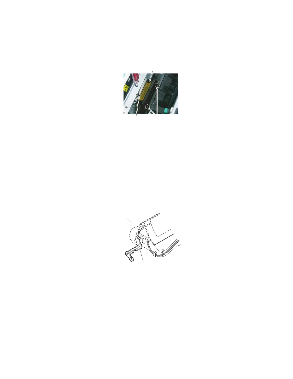
15. Press the Rack Release Lever and turn the Rack so that the screw securing the Laser (PH)
Unit to the chassis can be accessed through the hole [12] in the metal cross plate.
16. Remove three screws [12] and the Laser (PH) Unit [13].
Precautions for Reinstallation of the Laser (PH) Unit
Warning: When reinstalling the Laser (PH) Unit, make sure that you insert the lever [14] of
the Laser (PH) shutter into the lever of the machine [15].
Note:
■ Reconnect the blue connector (S5) before you reinstall the cover onto the printer.
■ To reinstall the ribbon cable, loosen the lower tab on the plastic air duct to give access
to the route.
Paper Take-Up Unit
1. Remove the Rear Cover. See Rear Cover on page 5-4.
2. Remove the Right Cover. See Right Cover on page 5-6.
3. Remove the Left Cover. See Left Cover on page 5-5.
4. Remove the High Voltage Unit. See High Voltage Unit (HV) on page 5-17.
[12]
[13]
[12]
4139fs2037c2
[15]
[14]
4139fs2539c0

 Loading...


