Error Codes and Messages Troubleshooting Procedures
Phaser® 6120 Color Laser Printer Service Manual
4-17
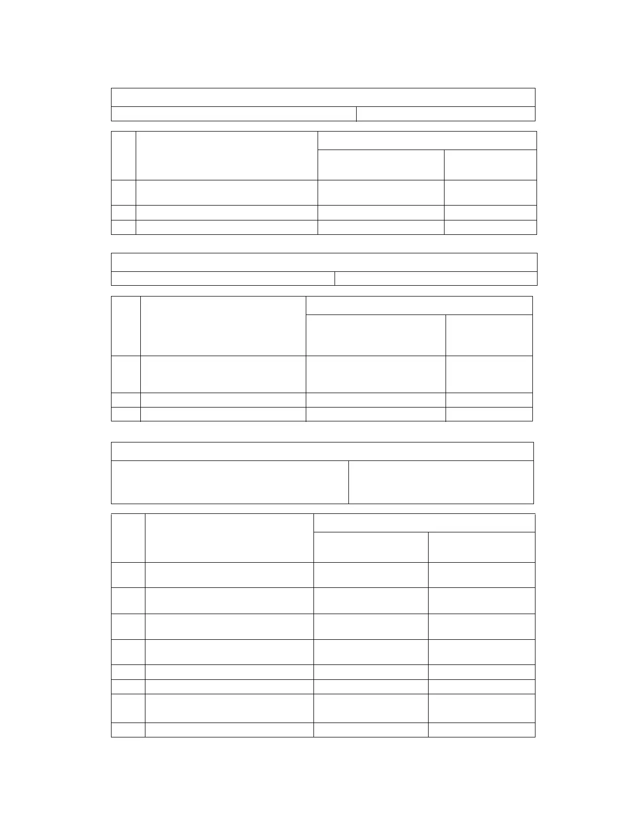
10: Polygon Motor (Laser) Malfunction
12: Laser Malfunction
14: Transfer Roller Failure
Relevant Electrical Parts
Laser Unit (PH) Unit PWB-A (Engine Control Board)
Step Action
WIRING DIAGRAM
Control Signal
Location (Electrical
Component)
1 Check the cables and connectors for proper
connection and correct as necessary.
--
2 Change Laser Unit (PH) Unit. - -
3 Change PWB-A. - -
Relevant Electrical Parts
Laser Unit (PH) Unit PWB-A (Engine Control Board)
Step Action
WIRING DIAGRAM
Control Signal
Location
(Electrical
Component)
1 Check the cables and connectors for
proper connection and correct as
necessary.
--
2 Change Laser Unit (PH) Unit. - -
3 Change PWB-A. - -
Relevant Electrical Parts
Retraction Position Sensor /2nd Image Transfer (PC5)
Pressure/Retraction Solenoid /2nd Image Transfer (SL4)
Main Motor (M1)
PWB-A (Engine Control Board)
Step Action
WIRING DIAGRAM
Control Signal
Location (Electrical
Component)
1 Check the M1 connector for proper
connection and correct as necessary.
--
2 Check M1 for proper drive coupling and
correct as necessary.
--
3 Check the SL4 connector for proper
connection and correct as necessary.
--
4 Check the PWB-A connector for proper
connection and correct as necessary.
--
5 PC5 sensor check. PWB-A PJ14A-3 (ON) 2-G
6 SL4 operation check. PWB-A PJ11A-2 (REM) 2-G
7 M1 operation check. PWB-A PJ8A-5 (REM)
PWB-A PJ8A-8 (LOCK)
2-G∼H
8 Change PWB-A. - -

 Loading...


