u
Main Circuit Terminal and Motor Wiring
This section outlines the various steps, precautions, and checkpoints for wiring the main circuit terminals and motor terminals.
WARNING! Electrical Shock Hazard. Do not connect the AC power line to the output terminals of the drive. Failure to comply could result
in death or serious injury by fire as a result of drive damage from line voltage application to output terminals.
NOTICE: When connecting the motor to the drive output terminals U/T1, V/T2, and W/T3, the phase order for the drive and motor should
match. Failure to comply with proper wiring practices may cause the motor to run in reverse if the phase order is backward.
NOTICE: Route motor leads U/T1, V/T2, and W/T3 separate from all other leads to reduce possible interference related issues. Failure to
comply may result in abnormal operation of drive and nearby equipment.
NOTICE: Do not connect phase-advancing capacitors or LC/RC noise filters to the output circuits. Failure to comply could result in damage
to the drive, phase-advancing capacitors, LC/RC noise filters or ground fault circuit interrupters.
n
Cable Length Between Drive and Motor
Voltage drop along the motor cable may cause reduced motor torque when the wiring between the drive and the motor is too
long, especially at low frequency output. This can also be a problem when motors are connected in parallel with a fairly long
motor cable. Drive output current will increase as the leakage current from the cable increases. An increase in leakage current
may trigger an overcurrent situation and weaken the accuracy of the current detection.
Adjust the drive carrier frequency according to Table 3.6. If the motor wiring distance exceeds 100 m because of the system
configuration, reduce the ground currents. Refer to C6-02: Carrier Frequency Selection on page 145.
Table 3.6 Cable Length Between Drive and Motor
Cable Length 50 m or less 100 m or less Greater than 100 m
Carrier Frequency 15 kHz or less 5 kHz or less 2 kHz or less
Note: 1. When setting carrier frequency for drives running multiple motors, calculate cable length as the total wiring distance to all connected
motors.
2. The maximum cable length when using OLV/PM (A1-02 = 5) or AOLV/PM (A1-02 = 6) is 100 m.
n
Ground Wiring
Follow the precautions below when wiring the ground for one drive or a series of drives.
WARNING! Electrical Shock Hazard. Make sure the protective earthing conductor complies with technical standards and local safety
regulations. Because the leakage current exceeds 3.5 mA in models 4A0414 and larger, IEC/EN 61800-5-1 states that either the power
supply must be automatically disconnected in case of discontinuity of the protective earthing conductor or a protective earthing conductor
with a cross-section of at least 10 mm
2
(Cu) or 16 mm
2
(Al) must be used. Failure to comply may result in death or serious injury.
WARNING! Electrical
Shock Hazard. Always use a ground wire that complies with technical standards on electrical equipment and minimize
the length of the ground wire. Improper equipment grounding may cause dangerous electrical potentials on equipment chassis, which could
result in death or serious injury.
WARNING! Electrical Shock Hazard. Be sure to ground the drive ground terminal (200 V class: ground to 100 Ω or less; 400 V class: ground
to 10 Ω or less; 600 V class: ground to 10 Ω or less). Improper equipment grounding could result in death or serious injury by contacting
ungrounded electrical equipment.
NOTICE: Do not share the ground wire with other devices such as welding machines or large-current electrical equipment. Improper
equipment grounding could result in drive or equipment malfunction due to electrical interference.
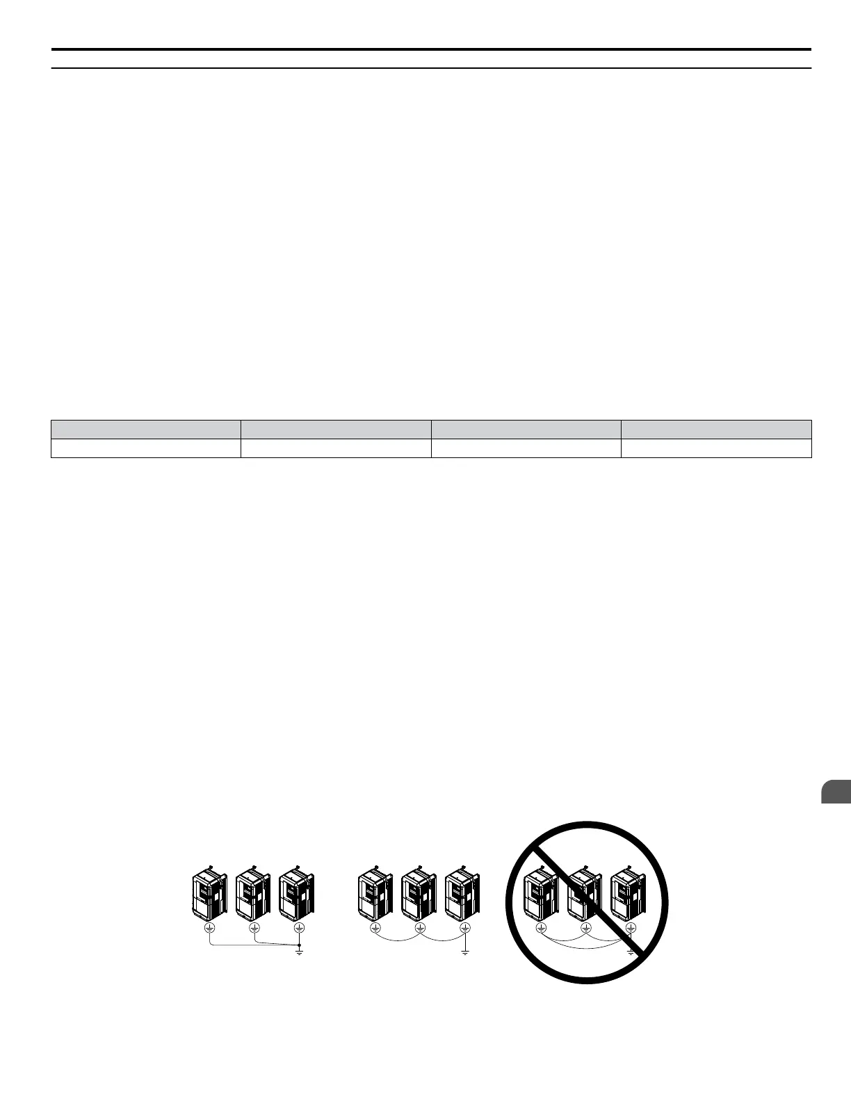
NOTICE: When using more than one drive, ground multiple drives according to instructions. Improper equipment grounding could result in
abnormal operation of drive or equipment.
Refer to Figure 3.24 when using multiple drives. Do not loop the ground wire.
Figure 3.24 Multiple Drive Wiring
3.6 Main Circuit Wiring
YASKAWA ELECTRIC TOEP C710616 41G YASKAWA AC Drive - A1000 Quick Start Guide
103
3
Electrical Installation

 Loading...


