u
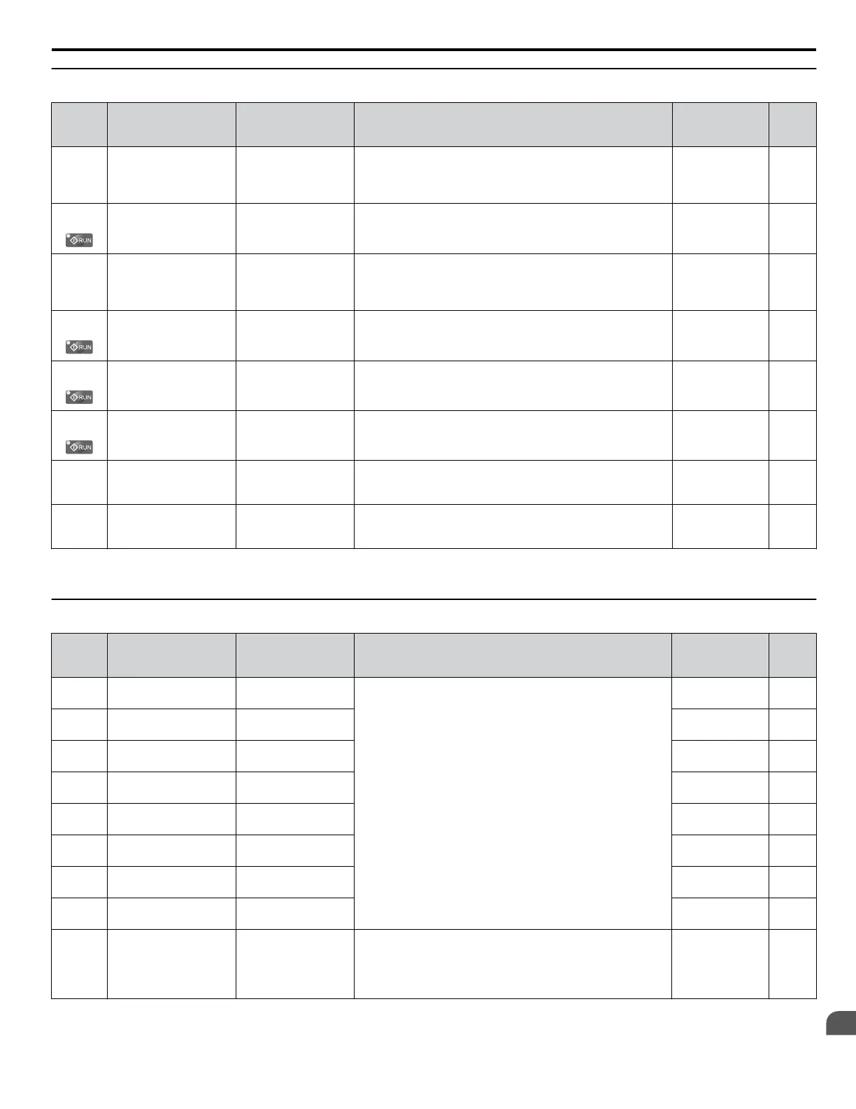
F4: Analog Monitor Card Settings (AO-A3)
No.
(Addr.
Hex)
Name LCD Display Description Values Page
F4-01
(0391)
Terminal V1 Monitor
Selection
AO Ch1 Select
Sets the monitor signal for output from terminal V1. Set this
parameter to the last three digits of the desired Uo-oo
monitor. Some U parameters are available only in certain
control modes.
Default: 102
Range:
000 to 999
<1>
–
F4-02
(0392)
Terminal V1 Monitor
Gain
AO Ch1 Gain
Sets the gain for voltage output via terminal V1.
Default: 100.0%
Min.: -999.9
Max.: 999.9
–
F4-03
(0393)
Terminal V2 Monitor
Selection
AO Ch2 Select
Sets the monitor signal for output from terminal V2. Set this
parameter to the last three digits of the desired Uo-oo
monitor. Some U parameters are available only in certain
control modes.
Default: 103
Range:
000 to 999
<1>
–
F4-04
(0394)
Terminal V2 Monitor
Gain
AO Ch2 Gain
Sets the gain for voltage output via terminal V2.
Default: 50.0%
Min.: -999.9
Max.: 999.9
–
F4-05
(0395)
Terminal V1 Monitor
Bias
AO Ch1 Bias
Sets the amount of bias added to the voltage output via terminal
V1.
Default: 0.0%
Min.: -999.9
Max.: 999.9
–
F4-06
(0396)
Terminal V2 Monitor
Bias
AO Ch2 Bias
Sets the amount of bias added to the voltage output via terminal
V2.
Default: 0.0%
Min.: -999.9
Max.: 999.9
–
F4-07
(0397)
Terminal V1 Signal
Level
AO Opt Level Ch1
0: 0-10 VDC
1: -10 +10 VDC
0: 0 to 10 V
1: -10 to 10 V
Default: 0
Range: 0, 1
–
F4-08
(0398)
Terminal V2 Signal
Level
AO Opt Level Ch2
0: 0-10 VDC
1: -10 +10 VDC
0: 0 to 10 V
1: -10 to 10 V
Default: 0
Range: 0, 1
–
<1> Set to 000 or 031 when using the terminal in the through mode. This setting can adjust the V1 and V2 terminal output from PLC via MEMOBUS/
Modbus communications or communications option.
u
F5: Digital Output Card Settings (DO-A3)
No.
(Addr.
Hex)
Name LCD Display Description Values Page
F5-01
(0399)
Terminal P1-PC Output
Selection
DO Ch1 Select
Sets the function for contact output terminals M1-M2, M3-M4,
and photocoupler output terminals P1 through P6.
Default: 2
Range: 0 to 192
–
F5-02
(039A)
Terminal P2-PC Output
Selection
DO Ch2 Select
Default: 4
Range: 0 to 192
–
F5-03
(039B)
Terminal P3-PC Output
Selection
DO Ch3 Select
Default: 6
Range: 0 to 192
–
F5-04
(039C)
Terminal P4-PC Output
Selection
DO Ch4 Select
Default: 37
Range: 0 to 192
–
F5-05
(039D)
Terminal P5-PC Output
Selection
DO Ch5 Select
Default: F
Range: 0 to 192
–
F5-06
(039E)
Terminal P6-PC Output
Selection
DO Ch6 Select
Default: F
Range: 0 to 192
–
F5-07
(039F)
Terminal M1-M2
Output Selection
DO Ch7 Select
Default: 0
Range: 0 to 192
–
F5-08
(03A0)
Terminal M3-M4
Output Selection
DO Ch8 Select
Default: 1
Range: 0 to 192
–
F5-09
(03A1)
DO-A3 Output Mode
Selection
DO Function Sel
0: Output terminals are each assigned separate output
functions.
1: Binary code output.
2:
Use output terminal functions selected by parameters F5-01
through F5-08.
Default: 0
Range: 0 to 2
–
B.6 F: Option Settings
YASKAWA ELECTRIC TOEP C710616 41G YASKAWA AC Drive - A1000 Quick Start Guide
281
B
Parameter List

 Loading...


