3.7 Control Circuit Wiring
u
Control Circuit Terminal Block Functions
Drive parameters determine which functions apply to the multi-function digital inputs (S1 to S8), multi-function digital outputs
(M1 to M6), multi-function analog inputs (A1 to A3), and multi-function analog monitor output (FM, AM). The default setting
is listed next to each terminal in Figure 3.1 on page 81.
WARNING! Sudden Movement Hazard. Always check the operation and wiring of control circuits after being wired. Operating a drive with
untested control circuits could result in death or serious injury.
WARNING! Sudden Movement Hazard. Confirm the drive I/O signals and external sequence before starting test run. Setting parameter
A1-06 may change the I/O terminal function automatically from the factory setting. Refer to Application Selection on page 134. Failure
to comply may result in death or serious injury.
n
Input Terminals
Table 3.7 lists the input terminals on the drive. Text in parenthesis indicates the default setting for each multi-function input.
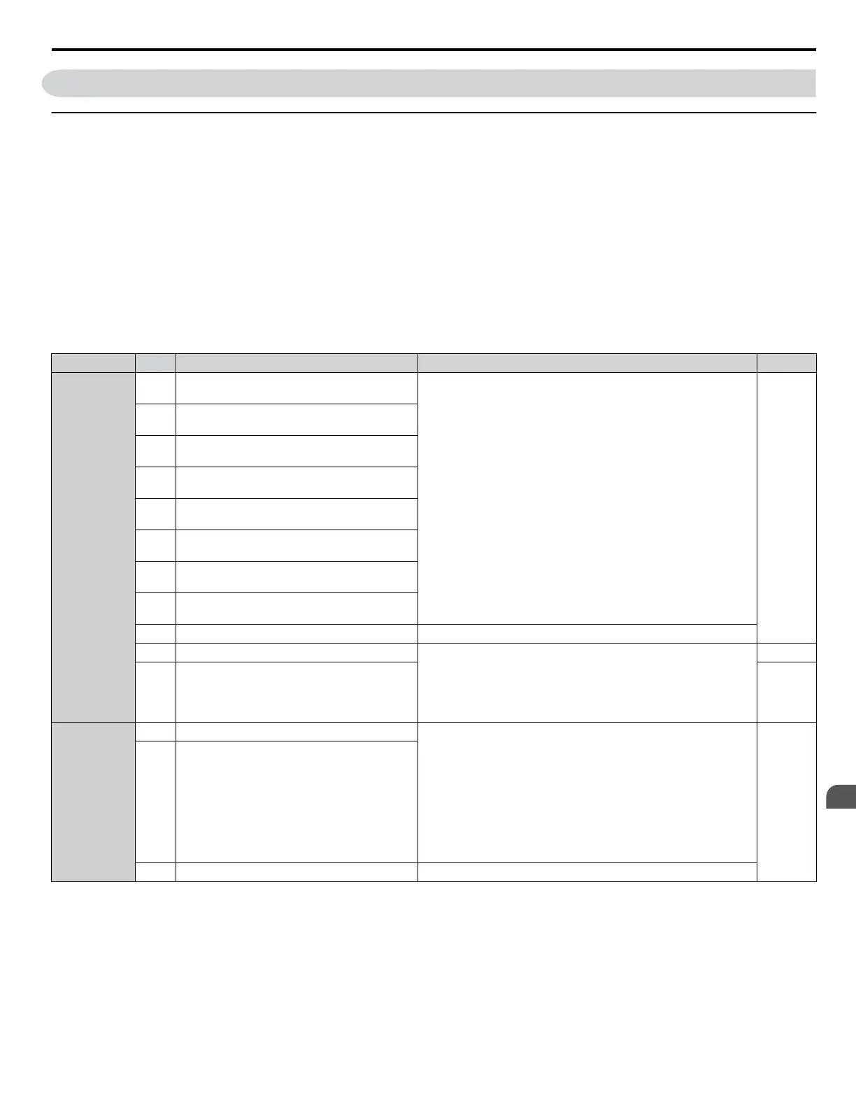
Table 3.7 Control Circuit Input Terminals
Type No. Terminal Name (Function) Function (Signal Level) Default Setting Page
Multi-Function
Digital Inputs
S1
Multi-function input 1
(Closed: Forward run, Open: Stop)
• Photocoupler
•
24 Vdc, 8 mA
• Refer to Sinking/Sourcing Mode for Digital Inputs on page
110.
288
S2
Multi-function input 2
(Closed: Reverse run, Open: Stop)
S3
Multi-function input 3
(External fault, N.O.)
S4
Multi-function input 4
(Fault reset)
S5
Multi-function input 5
(Multi-step speed reference 1)
S6
Multi-function input 6
(Multi-step speed reference 2)
S7
Multi-function input 7
(Jog reference)
S8
Multi-function input 8
(Baseblock command (N.O.))
SC Multi-function input common Multi-function input common
SP Digital input power supply +24 Vdc 24 Vdc power supply for digital inputs, 150 mA max (only when
not using digital input option DI-A3)
NOTICE: Do not jumper or short terminals SP and SN.
Failure to comply will damage the drive.
110
SN Digital input power supply 0 V 110
Safe Disable
Inputs
H1 Safe Disable input 1 • 24 Vdc, 8 mA
•
One or both open: Output disabled
• Both closed: Normal operation
• Internal impedance: 3.3 kΩ
• Off time of at least 1 ms
• Disconnect the wire jumpers shorting terminals H1, H2, and HC
to use the Safe Disable inputs. Set the S3 jumper to select
between sinking, sourcing mode, and the power supply as
explained on page 110.
352H2 Safe Disable input 2
HC Safe Disable function common Safe disable function common
3.7 Control Circuit Wiring
YASKAWA ELECTRIC TOEP C710616 41G YASKAWA AC Drive - A1000 Quick Start Guide
105
3
Electrical Installation

 Loading...


