+
-
+
-
+
+
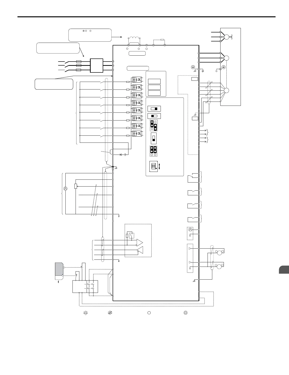
Terminals , +1, +2, B1, B2 are
for connection options. Never
connect power supply lines to
these terminals
DC link choke
(option)
U X
+
-
+
-
+
+
+
-
U X
S1
S2
S3
S4
S5
S6
S7
MP
DM
DM
RP
A1
A2
A3
0 V
AC
R
R
S
S-
IG
H1
H2
HC
Drive
B112
B2
2 k
S8
SC
0 V
0 V
AC
FM
AM
AC
E (G)
S1
S2
<1>
<2>
<11>
<6>
<12>
<13>
<8>
<10>
<6>
<4>
<3>
-
+24 V
+V
MA
M1
M2
MB
MC
Jumper
Braking resistor
(option)
Forward Run / Stop
Reverse Run / Stop
External fault
Fault reset
Multi-speed step 1
Multi-speed step 2
External Baseblock
Jog speed
Multi-function
digtial inputs
(default setting)
Sink / Source mode
selection wire link
(default: Sink)
CN5-C
CN5-B
CN5-A
Option board
Pulse Train Input
(max 32 kHz)
Shield ground
terminal
Multi-function
analog/pulse
train inputs
Power supply +10.5 Vdc, max. 20 mA
Analog Input 1 (Frequency Reference Bias)
-10 to +10 Vdc (20 k )
Analog Input 2 (Frequency Reference Bias)
-10 to +10 Vdc (20 k )
0 or 4 to 20 mA (250 )
Analog Input 3 / PTC Input (Aux. frequency
reference)
-10 to +10 Vdc (20 k )
-V
Power supply, -10.5 Vdc, max. 20 mA
Safety
switch
MEMOBUS/Modbus comm.
RS-422/RS-485
max. 115.2 kBps
Safe Disable inputs
Wire
jumper
Open
Safety relay /
controller
Termination resistor
(120 , 1/2 W)
DIP
Switch S2
Fault relay output
250 Vac, max. 1 A
30 Vdc, max 1 A
(min. 5 Vdc, 10 mA)
Multi-function relay output (During Run)
250 Vac, max. 1 A
30 Vdc, max 1 A
(min. 5 Vdc, 10 mA)
Multi-function pulse train output
(Output frequency)
0 to 32 kHz (2.2 k )
Multi-function analog output 1
(Output frequency)
-10 to +10 Vdc (2mA)
or 4 to 20 mA
EDM (Safety Electronic Device Monitor)
Main Circuit
Control Circuit
shielded line
twisted-pair shielded line
main circuit terminal
control circuit terminal
R/L1
S/L2
T/L3
R
S
T
Main
Switch
Fuse
EMC
Filter
M3
M4
Multi-function relay output (Zero Speed)
250 Vac, max. 1 A
30 Vdc, max 1 A
(min. 5 Vdc, 10 mA)
M5
M6
Multi-function relay output (Speed Agree 1)
250 Vac, max. 1 A
30 Vdc, max 1 A
(min. 5 Vdc, 10 mA)
SP
SN
<9>
AMFM
V
I
V
I
DIP Switch S1
A2 Volt/Curr. Sel
DIP Switch S4
A3 Analog/PTC
Input Sel
PTC
AI
Off
On
DIP Switch S2
Term. Res. On/Off
Jumper S3
H1, H2
Sink/Source Sel.
Jumper S5
AM/FM Volt./Curr.
Selection
Terminal board
jumpers and switches
FM
+
-
AM
<5>
<14>
Ω
Ω
Ω
Ω
Ω
Ω
<13>
Multi-function analog output 2
(Output current)
-10 to +10 Vdc (2mA)
or 4 to 20 mA
Three-Phase
Power Supply
200 to 600 V
50/60 Hz
<15>
<6>
A+
A-
B-
Z-
B+
Z+
a+
a-
b+
b-
z+
z-
FE
IP
IG
TB1
SD
TB2
B track monitor
A track monitor
M
U/T1
V/T2
W/T
U
FU
FV
FW
V
W
3
Ground
Cooling fan
PG
M
PG- X3
connectors
(option)
Wiring sequence should shut off
power to the drive when a fault
output is triggered.
(Depending on
model capacity)
Ω
Models 4A0930 and 4A1200
are compatible with
12-Phase Rectification.
Slide Switch S6
DM+, DM-
N.C./N.O. Selection
N.C.
N.O.
<7>
++
Remove the jumper when installing a DC link choke. Models 2A0110 to 2A0415 and 4A0058 to 4A1200 come with a built-in
DC link choke.

 Loading...


