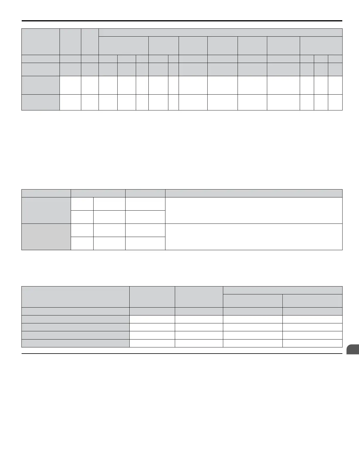
Input Value
Input
Param.
Unit
Tuning Type (T2-01)
0
Motor Parameter
Settings
1
Stationary
2
Stationary
Stator Resis.
3
Z-Pulse
Offset
11
Back EMF
Const.
13
High Freq.
Injection
14
Rotational
Control Mode A1-02 – 5, 6, 7 5 6, 7 5 6, 7 5, 6, 7 7 7 6, 7 5 6 7
Motor Code
(Hex.)
T2-02 –
<1> <1> <1>
– – – – – – – – –
PG Number of
Pulses Per
Revolution
T2-16 ppr
YES
<2>
–
YES
<2>
–
YES
<2>
– – – – – – YES
Z Pulse Offset T2-17
deg
(mech.)
YES
<2>
–
YES
<2>
–
YES
<2>
– – – – – – –
<1> Input the motor code when using a Yaskawa motor. Select “FFFF” when using a motor from another manufacturer.
<2>
Input data is needed for CLV/PM only.
<3> Dependent upon T2-13 setting.
n
Inertia Tuning and Speed Control Loop Auto-Tuning
Inertia Tuning can be performed when the drive is using CLV control for either IM or PM motors. Inertia Tuning automatically
calculates load and motor inertia, and optimizes settings related to the KEB Ride-Thru function (KEB 2) and Feed Forward
control.
ASR Gain Auto-Tuning performs the same operation as Inertia Tuning, while also optimizing speed control loop settings.
Table 4.32 Inertia and Speed Control Loop Tuning
Type Setting Control Mode Application Conditions and Benefits
Inertia Tuning
IM
Motor
T1-01 = 8 CLV
Allows the motor to rotate at a certain speed and applies a test signal. The response
to
the test signal is analyzed and the necessary adjustments are made to parameters
controlling the Feed Forward and KEB Ride-Thru functions (KEB 2, L2-29 = 1).
PM
Motor
T2-01 = 8 CLV/PM
ASR Gain Auto-
Tuning
IM
Motor
T1-01 = 9 CLV
Performs the same operation as Inertia Tuning, while also adjusting the ASR gain
according to the test signal response.
PM
Motor
T2-01 = 9 CLV/PM
Note: Inertia Tuning and ASR Gain Auto-Tuning may not be available when gears are between the machine and the motor shaft.
Table 4.33 explains the data that must be entered to perform the Inertia Tuning and ASR Gain Auto-Tuning. Refer to Auto-
Tuning for Permanent Magnet Motors on page 165 for details.
Table 4.33
Auto-Tuning Input Data
Input Value Input Parameter Unit
Tuning Type (T1-01 or T2-01)
8
Inertia Tuning
9
ASR Gain Tuning
Control Mode A1-02 – 3, 7 3, 7
Test signal frequency T3-01 Hz YES YES
Test signal amplitude T3-02 rad YES YES
Motor inertia T3-03
kgm
2
YES YES
System response frequency T3-04 Hz – YES
u
Auto-Tuning Interruption and Fault Codes
If tuning results are abnormal or the STOP key is pressed before completion, Auto-Tuning will be interrupted and a fault code
will appear on the digital operator.
4.7 Auto-Tuning
YASKAWA ELECTRIC TOEP C710616 41G YASKAWA AC Drive - A1000 Quick Start Guide
167
4
Start-Up Programming
& Operation

 Loading...


