u
LCD Display
]
7
6
5
1 2 3 4
8910
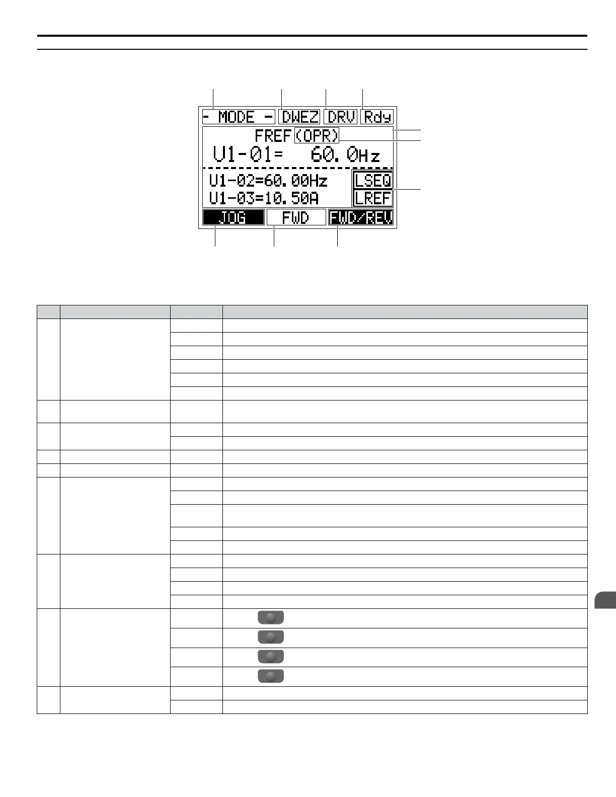
Figure 4.2 LCD Display
Table 4.1 Display and Contents
No. Name Display Content
1 Operation Mode Menus
MODE Displayed when in Mode Selection.
MONITR Displayed when in Monitor Mode.
VERIFY Indicates the Verify Menu.
PRMSET Displayed when in Parameter Setting Mode.
A.TUNE Displayed during Auto-Tuning.
SETUP Displayed when in Setup Mode.
2
DriveWorksEZ
Function Selection
DWEZ Displayed when DriveWorksEZ is set to enable. (A1-07 = 1 or 2)
3 Mode Display Area
DRV Displayed when in Drive Mode.
PRG Displayed when in Programming Mode.
4 Ready Rdy Indicates the drive is ready to run.
5 Data Display — Displays specific data and operation data.
6
Frequency
Reference
Assignment
<1>
OPR Displayed when the frequency reference is assigned to the LCD Operator Option.
AI Displayed when the frequency reference is assigned to the Analog Input of the drive.
COM
Displayed when the frequency reference is assigned to the MEMOBUS/Modbus Communication
Inputs of the drive.
OP Displayed when the frequency reference is assigned to an Option Unit of the drive.
RP Displayed when the frequency reference is assigned to the Pulse Train Input of the drive.
7
LO/RE
Display
<2>
RSEQ Displayed when the run command is supplied from a remote source.
LSEQ Displayed when the run command is supplied from the operator keypad.
RREF Displayed when the frequency reference is supplied from a remote source.
LREF Displayed when the frequency reference is supplied from the operator keypad.
8
Function Key 2
(F2)
FWD/REV
Pressing
F2
switches between forward and reverse.
DATA
Pressing
F2
scrolls to the next display.
→
Pressing
F2
scrolls the cursor to the right.
RESET
Pressing
F2
resets the existing drive fault error.
9 FWD/REV
FWD Indicates forward motor operation.
REV Indicates reverse motor operation.
4.1 Using the Digital Operator
YASKAWA ELECTRIC TOEP C710616 41G YASKAWA AC Drive - A1000 Quick Start Guide
121
4
Start-Up Programming
& Operation

 Loading...


