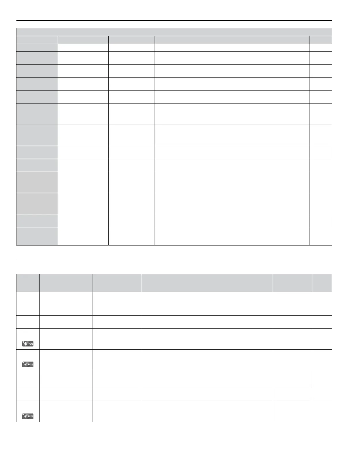
H2 Multi-Function Digital Output Settings
H2-oo Setting
Function LCD Display Description Page
3F PID feedback high PID FeedbackHigh Closed: The PID feedback level is too high. –
4A
During KEB Ride-
Thru
During KEB
Closed: KEB Ride-Thru is being performed.
–
4B
During short circuit
braking
During SC Brake
Closed: Short Circuit Braking is active.
–
4C During fast stop During Fast Stop
Closed: A Fast Stop command has been entered from the operator or input
terminals.
–
4D
oH Pre-alarm time
limit
OH Pre-Alarm
Closed: oH pre-alarm time limit has passed.
–
4E
Braking transistor fault
(rr)
Brk Trans Fault
Closed: The built-in dynamic braking transistor failed.
Note: This setting is not available in models 2A0169 to 2A0415
and 4A0088 to 4A1200.
–
4F
Braking resistor
overheat (oH)
BrkResistOvHeat
Closed: The dynamic braking resistor has overheated.
Note: This setting is not available in models 2A0169 to 2A0415
and 4A0088 to 4A1200.
–
60
Internal cooling fan
alarm
Fan Alrm Det
Closed: Internal cooling fan alarm
–
61
Rotor position
detection complete
RotPosDetCmpIt
Closed: Drive has successfully detected the rotor position of the PM motor.
–
62
<1>
MEMOBUS Register 1
(Selected with H2-07
and H2-08)
Memobus Regs1
The contact output is closed when any of the bits specified by H2-08 for
the MEMOBUS/Modbus register address set in H2-07 turn on.
Note: This setting is not available in models 4A0930 and 4A1200.
–
63
<1>
MEMOBUS Register 2
(Selected with H2-09
and H2-10)
Memobus Regs2
The contact output is closed when any of the bits specified by H2-10 for
the MEMOBUS/Modbus register address set in H2-09 turn on.
Note: This setting is not available in models 4A0930 and 4A1200.
–
90 to 92
DriveWorksEZ
digital outputs 1 to 3
–
Reserved for DWEZ digital output functions.
–
100 to 192
Function 0 to 92 with
inverse output
!Function
Inverts the output switching of the multi-function output functions.
Set the last two digits of 1oo to reverse the output signal of that specific
function.
–
<1> Available in drive software versions PRG: 1019 and later.
u
H3: Multi-Function Analog Inputs
No.
(Addr.
Hex)
Name LCD Display Description Values Page
H3-01
(0410)
Terminal A1 Signal
Level Selection
Term A1 Level
0: 0-10V,
(LowLim=0)
1: 0-10V, (BipolRef)
0: 0 to 10 V
1: -10 to 10 V Default: 0
Range: 0, 1
155
H3-02
(0434)
Terminal A1 Function
Selection
Term A1 FuncSel
Sets the function of terminal A1. Default: 0
Range: 0 to 32
155
H3-03
(0411)
Terminal A1 Gain
Setting
Terminal A1 Gain
Sets the level of the input value selected in H3-02 when 10 V
is input at terminal A1.
Default: 100.0%
Min.: -999.9
Max.: 999.9
156
H3-04
(0412)
Terminal A1 Bias
Setting
Terminal A1 Bias
Sets the level of the input value selected in H3-02 when 0 V is
input at terminal A1.
Default: 0.0%
Min.: -999.9
Max.: 999.9
156
H3-05
(0413)
Terminal A3 Signal
Level Selection
Term A3 Signal
0: 0-10V (LowLim=0)
1: 0-10V, (BipolRef)
0: 0 to 10 V
1: -10 to 10 V
Default: 0
Range: 0, 1
156
H3-06
(0414)
Terminal A3 Function
Selection
Terminal A3 Sel
Sets the function of terminal A3. Default: 2
Range: 0 to 32
156
H3-07
(0415)
Terminal A3 Gain
Setting
Terminal A3 Gain
Sets the level of the input value selected in H3-06 when 10 V
is input at terminal A3.
Default: 100.0%
Min.: -999.9
Max.: 999.9
157
B.7 H Parameters: Multi-Function Terminals
294
YASKAWA ELECTRIC TOEP C710616 41G YASKAWA AC Drive - A1000 Quick Start Guide

 Loading...


