Table 3.2 Input Fuses for Models 4A0930 and 4A1200
Voltage
Class
Model
Selection Input Fuse (Example)
Input Voltage Current
Pre-arc
I
2
t (A
2
s)
Model Manufacturer Rating
Pre-arc
I
2
t (A
2
s)
Three-
Phase
400 V
Class
4A0930
480 V 1500 A
140000 to
3100000
CS5F-1200 Fuji Electric AC500 V, 1200 A 276000
4A0930 with
12-pulse
rectification
FWH-1200A Bussman AC500 V, 1200 A –
FWH-1000A Bussman AC500 V, 1000 A –
4A1200
480 V 1500 A
320000 to
3100000
CS5F-1500 Fuji Electric AC500 V, 1500 A 351000
4A1200 with
12-pulse
rectification
FWH-1600A Bussman AC500 V, 1600 A –
FWH-1200A Bussman AC500 V, 1200 A –
u
Protecting Main Circuit Terminals
n
Insulation Caps or Sleeves
Use
insulation caps or sleeves when wiring the drive with crimp terminals. Take particular care to ensure that the wiring does
not touch nearby terminals or the surrounding case.
n
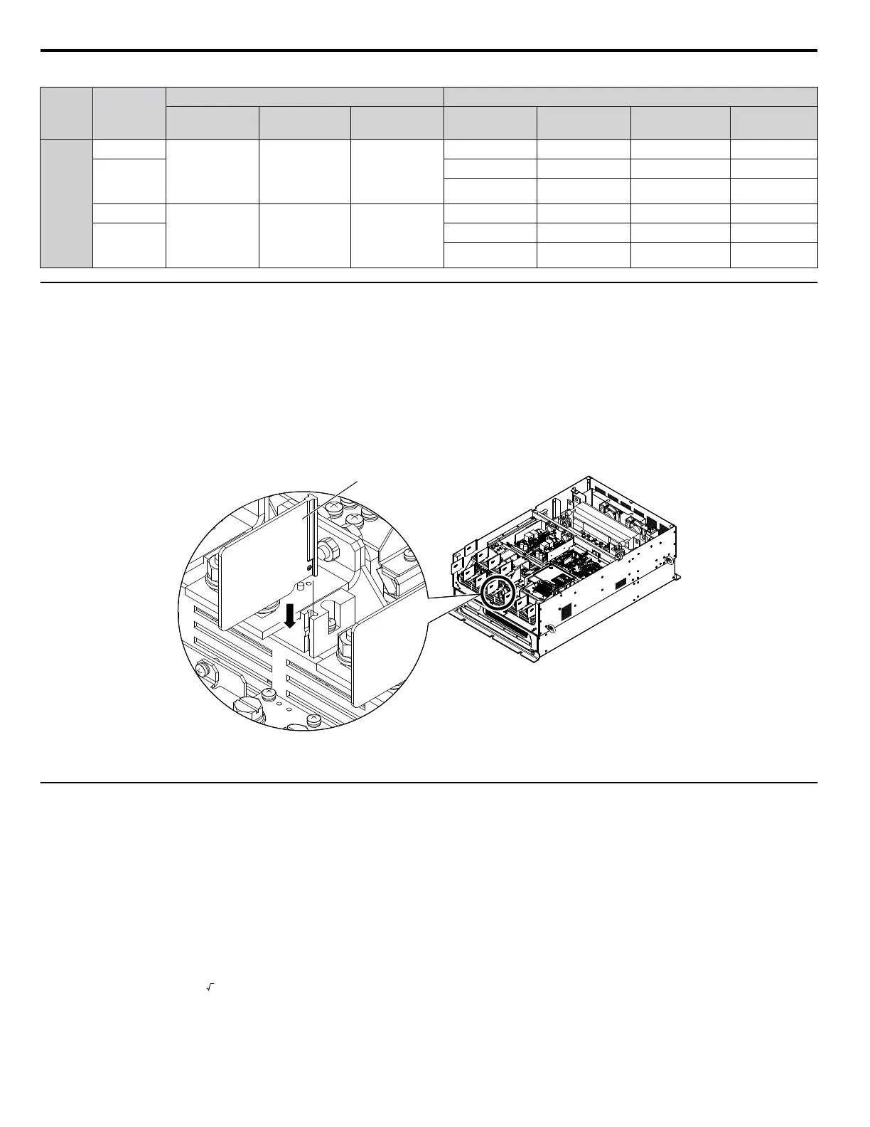
Insulation Barrier
Insulation barriers are packaged with drive models 4A0414 through 4A1200 to provide added protection between terminals.
Yaskawa recommends using the provided insulation barriers to ensure proper wiring. Refer to Figure 3.23 for instructions on
placement of the insulation barriers.
Insulation Barrier
Figure 3.23 Installing Insulation Barriers
u
Main Circuit Wire Gauges and Tightening Torques
Use the tables in this section to select the appropriate wires and crimp terminals.
Gauges listed in the tables are for use in the United States.
Note:
1. Wire gauge recommendations based on drive continuous current ratings (ND) using 75 °C 600 Vac vinyl-sheathed wire assuming ambient
temperature within 40 °C and wiring distance less than 100 m.
2. Terminals ⊕1, ⊕2, ⊕3, ⊖, B1 and B2 are for connecting optional power devices. Use caution to connect only approved devices to the
correct terminal(s).
• Consider the amount of voltage drop when selecting wire gauges. Increase the wire gauge when the voltage drop is greater
than 2% of motor rated voltage. Ensure the wire gauge is suitable for the terminal block. Use the following formula to
calculate the amount of voltage drop:
Line drop voltage (V) =
3 × wire resistance (Ω/km) × wire length (m) × current (A) × 10
-3
•
Refer to instruction manual TOBPC72060000 or TOBPC72060001 for braking transistor option or braking resistor option
wire gauges.
• Use terminals ⊕1 and ⊖ when connecting a regenerative converter or a regen unit.
3.6 Main Circuit Wiring
94
YASKAWA ELECTRIC TOEP C710616 41G YASKAWA AC Drive - A1000 Quick Start Guide

 Loading...


