3.3 Terminal Cover
Follow
the procedure below to remove the terminal cover for wiring and to reattach the terminal cover after wiring is complete.
u
Models 2A0004 to 2A0081, 4A0002 to 4A0044, 5A0003 to 5A0032 (IP20/NEMA 1, UL Type
1 Enclosure)
n
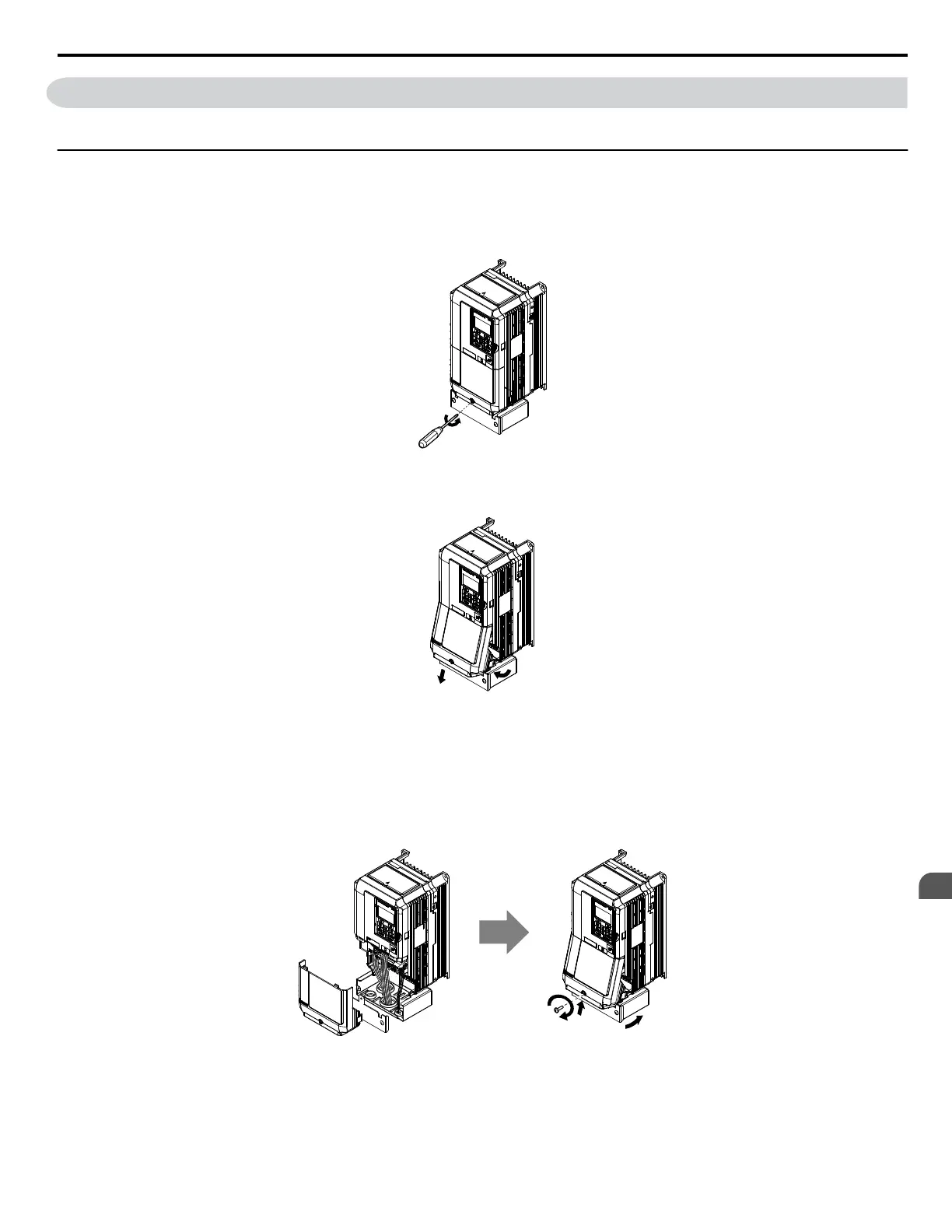
Removing the Terminal Cover
1.
Loosen the terminal cover screw using a #2 Phillips screwdriver. Screw sizes vary by drive model.
Figure 3.9 Removing the Terminal Cover on an IP20/NEMA 1, UL Type 1 Enclosure Drive
2.
Push in on the tab located on the bottom of the terminal cover and gently pull forward to remove the terminal cover.
Figure 3.10 Removing the Terminal Cover on an IP20/NEMA 1, UL Type 1 Enclosure Drive
n
Reattaching the Terminal Cover
Power lines and signal wiring should pass through the opening provided. Refer to Wiring the Main Circuit Terminal
on
page 104 and Wiring the Control Circuit Terminal on page 108 for details on wiring.
Reattach the terminal cover after completing the wiring to the drive and other devices.
Figure 3.11 Reattaching the Terminal Cover on an IP20/NEMA 1, UL Type 1 Enclosure Drive
<1> Connect the ground wiring first, then the main circuit wiring, and finally the control circuit wiring.
3.3 Terminal Cover
YASKAWA ELECTRIC TOEP C710616 41G YASKAWA AC Drive - A1000 Quick Start Guide
87
3
Electrical Installation

 Loading...


