n
Ferrule-Type Wire Terminals
Yaskawa recommends using CRIMPFOX 6, a crimping tool manufactured by PHOENIX CONTACT, to prepare wire ends
with insulated sleeves before connecting to the drive. See Table 3.11 for dimensions.
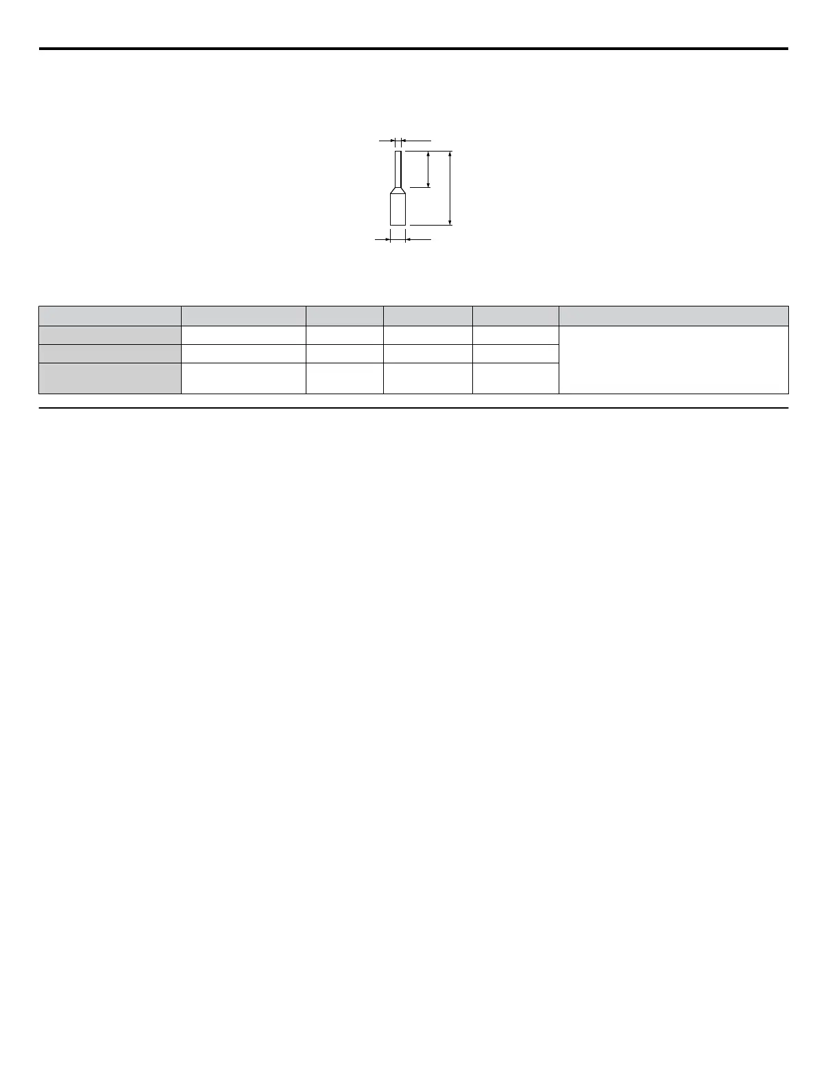
Figure 3.27 Ferrule Dimensions
Table 3.11 Ferrule Terminal Types and Sizes
Size mm
2
(AWG)
Type L mm (in) d1 mm (in) d2 mm (in) Manufacturer
0.25 (24) AI 0.25-8YE 12.5 (0.49) 0.8 (0.03) 2.0 (0.08)
PHOENIX CONTACT
0.34 (22) AI 0.34-8TQ 12.5 (0.49) 0.8 (0.03) 2.0 (0.08)
0.5 (20)
AI 0.5-8WH
AI 0.5-8OG
14.0 (0.55) 1.1 (0.04) 2.5 (0.10)
u
Wiring the Control Circuit Terminal
This section describes the proper procedures and preparations for wiring the control terminals.
WARNING! Electrical
Shock Hazard. Do not remove covers or touch the circuit boards while the power is on. Failure to comply could result
in death or serious injury.
NOTICE: Separate control circuit wiring from main circuit wiring (terminals R/L1, S/L2, T/L3, B1, B2, U/T1, V/T2, W/T3,
⊖
,
⊕
1,
⊕
2) and
other high-power lines. Improper wiring practices could result in drive malfunction due to electrical interference.
NOTICE: Separate wiring for digital output terminals MA, MB, MC, and M1 to M6 from wiring to other control circuit lines. Improper wiring
practices could result in drive or equipment malfunction or nuisance trips.
NOTICE: Use a class 2 power supply when connecting to the control terminals. Improper application of peripheral devices could result in
drive performance degradation due to improper power supply. Refer to NEC Article 725 Class 1, Class 2, and Class 3 Remote-Control,
Signaling, and Power Limited Circuits for requirements concerning class 2 power supplies.
NOTICE: Insulate shields with tape or shrink tubing to prevent contact with other signal lines and equipment. Improper wiring practices could
result in drive or equipment malfunction due to short circuit.
NOTICE: Connect the shield of shielded cable to the appropriate ground terminal. Improper equipment grounding could result in drive or
equipment malfunction or nuisance trips.
NOTICE: Do not tighten screws beyond the specified tightening torque. Failure to comply may result in erroneous operation, damage to the
terminal block, or cause a fire.
NOTICE: Use shielded twisted-pair cables as indicated to prevent operating faults. Improper wiring practices could result in drive or
equipment malfunction due to electrical interference.
Wire the control circuit only after terminals have been properly grounded and main circuit wiring is complete. Refer to
Terminal Board Wiring Guide on page 109 for details. Prepare the ends of the control circuit wiring as shown in Figure
3.30. Refer to Wire Gauges on page 107.
Connect control wires as shown in Figure 3.28 and Figure 3.29.
3.7 Control Circuit Wiring
108
YASKAWA ELECTRIC TOEP C710616 41G YASKAWA AC Drive - A1000 Quick Start Guide

 Loading...


