u
Terminal A2 Input Signal Selection
Terminal A2 can be used to input either a voltage or a current signal. Select the signal type using switch S1 as explained in
Table 3.14. Set parameter H3-09 accordingly as shown in Table 3.15.
Note: If terminals A1 and A2 are both set for frequency bias (H3-02 = 0 and H3-10 = 0), both input values will be combined to create the frequency
reference.
Table 3.14 DIP Switch S1 Settings
Setting Description
V (left position) Voltage input (-10 to +10 V or 0 to 10 V)
I (right position) Current input (4 to 20 mA or 0 to 20 mA): default setting
Table 3.15 Parameter H3-09 Details
No. Parameter Name Description Setting Range Default Setting
H3-09 Terminal A2 Signal Level Selection
Selects the signal level for terminal A2.
0: 0 to 10 Vdc
1: -10 to 10 Vdc
2: 4 to 20 mA
3: 0 to 20 mA
0 to 3 2
u
Terminal A3 Analog/PTC Input Selection
Terminal A3 can be configured either as multi-function analog input or as PTC input for motor thermal overload protection.
Use switch S4 to select the input function as described in Table 3.16.
Table 3.16
DIP Switch S4 Settings
Setting Description
AI (lower position) (default) Analog input for the function selected in parameter H3-06
PTC (upper position) PTC input. Parameter H3-06 must be set to E (PTC input)
u
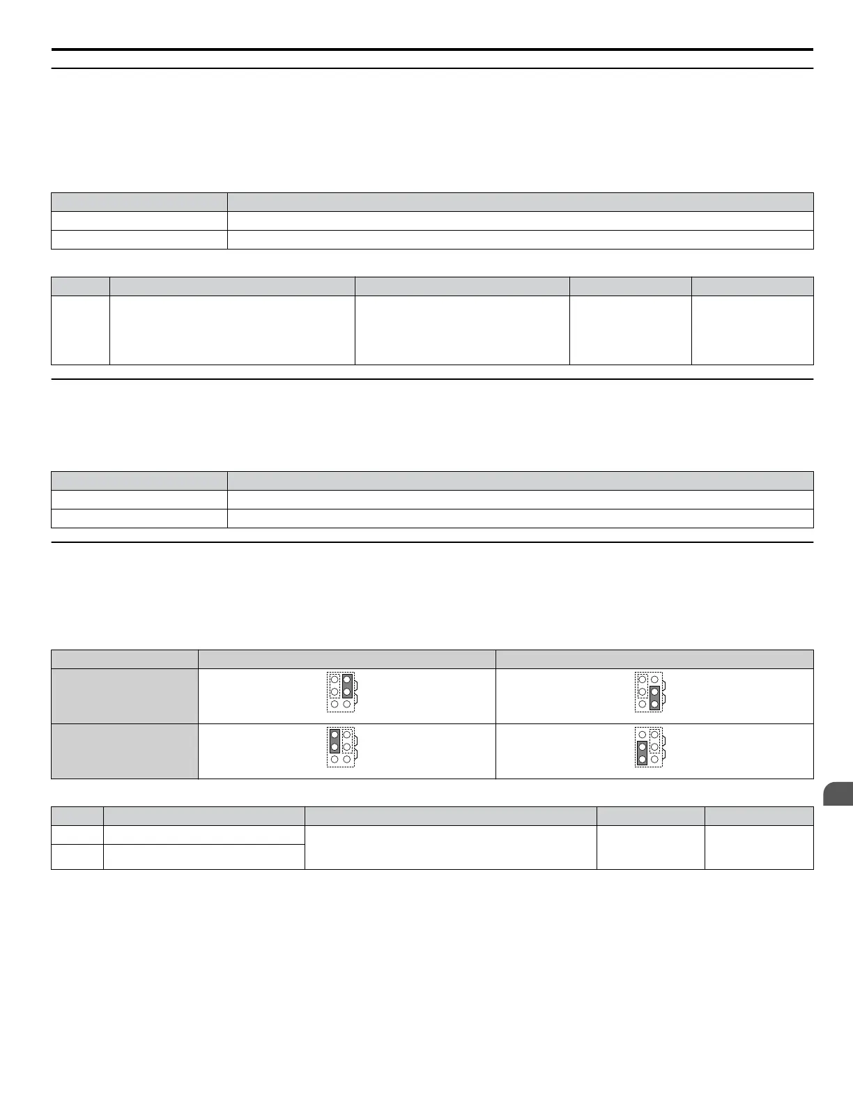
Terminal AM/FM Signal Selection
The signal type for terminals AM and FM can be set to either voltage or current output using jumper S5 on the terminal board
as explained in Table 3.17. When changing the setting of jumper S5, parameters H4-07 and H4-08 must be set accordingly.
The default selection is voltage output for both terminals.
Table 3.17 Jumper S5 Settings
Terminal Voltage Output Current Output
Terminal AM
AMFM
V
I
AMFM
V
I
Terminal FM
AMFM
V
I
AMFM
V
I
Table 3.18 Parameter H4-07 and H4-08 Details
No. Parameter Name Description Setting Range Default Setting
H4-07 Terminal FM signal level selection 0: 0 to 10 Vdc
1: -10 to 10 Vdc
2: 4 to 20 mA
0 to 2 0
H4-08 Terminal AM signal level selection
3.8 Control I/O Connections
YASKAWA ELECTRIC TOEP C710616 41G YASKAWA AC Drive - A1000 Quick Start Guide
113
3
Electrical Installation

 Loading...


