n
H3-03, H3-04: Terminal A1 Gain and Bias Settings
Parameter H3-03 sets the level of the selected input value that is equal to 10 Vdc input at terminal A1 (gain).
Parameter H3-04 sets the level of the selected input value that is equal to 0 V input at terminal A1 (bias).
Use both parameters to adjust the characteristics of the analog input signal to terminal A1.
No. Name Setting Range Default
H3-03 Terminal A1 Gain Setting -999.9 to 999.9% 100.0%
H3-04 Terminal A1 Bias Setting -999.9 to 999.9% 0.0%
Setting Examples
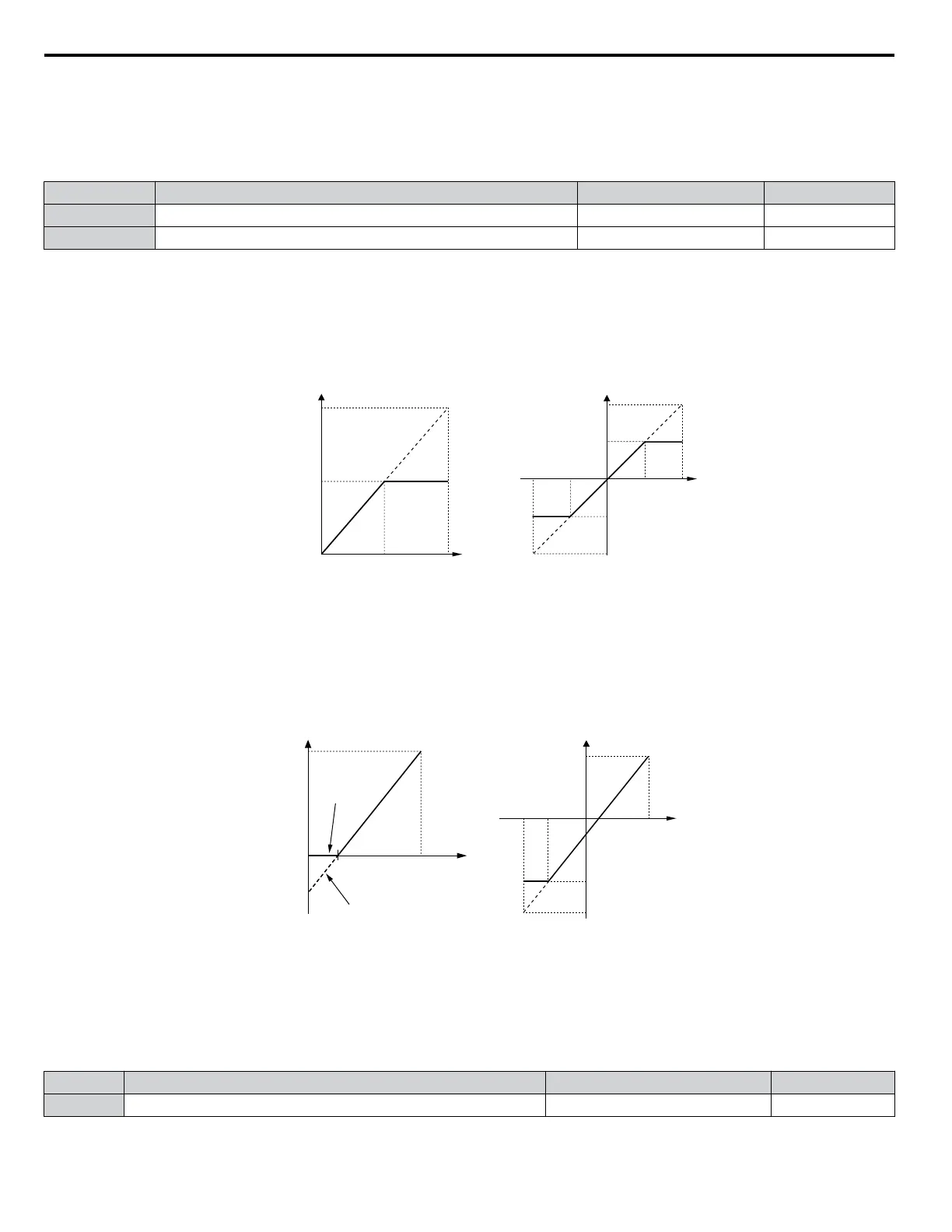
• Gain H3-03 = 200%, bias H3-04 = 0, terminal A1 as frequency reference input (H3-02 = 0):
A 10 Vdc input is equivalent to a 200% frequency reference and 5 Vdc is equivalent to a 100% frequency reference. Since
the drive output is limited by the maximum frequency parameter (E1-04), the frequency reference will be equal to E1-04
above 5 Vdc.
100%
-100%
5 V
10 V
-5 V-10 V
E1-04
E1-04
H3-01 = 0 H3-01 = 1
0 V
10 V5 V
0 V
Gain = 200 % Gain = 200 %
100 %
Frequency
reference
Bias = 0 %
E1-04
Gain = -200 %
Figure 4.29 Frequency Reference Setting by Analog Input with Increased Gain
• Gain H3-03 = 100%, bias H3-04 = -25%, terminal A1 as frequency reference input:
An input of 0 Vdc will be equivalent to a -25% frequency reference.
When parameter H3-01 = 0, the frequency reference is 0% between 0 and 2 Vdc input.
When parameter H3-01 = 1, the motor will rotate in reverse between -10 and 2 Vdc input.
2.0 V
10 V
-6.0 V-10 V
E1-04
0
-100%
-150%
2.0 V 10 V
100 %
Frequency
reference
-25%
-25%
H3-01 = 0
H3-01 = 1
H3-01 = 0 H3-01 = 1
100%
Analog Input
V
oltage
Analog Input
Voltage
Figure 4.30 Frequency Reference Setting by Analog Input with Negative Bias
n
H3-05:
Terminal A3 Signal Level Selection
Selects the input signal level for analog input A3.
Be sure to set DIP switch S4 on the terminal board accordingly for multi-function analog input or PTC input. Also Refer to
Terminal A3 Analog/PTC Input Selection on page 113.
No. Name Setting Range Default
H3-05 Terminal A3 Signal Level Selection 0, 1 0
Setting 0: 0 to 10 Vdc
The input level is 0 to 10 Vdc. See the explanation provided for H3-01. Refer to Setting 0: 0 to 10 Vdc
on page 155.
4.6 Basic Drive Setup Adjustments
156
YASKAWA ELECTRIC TOEP C710616 41G YASKAWA AC Drive - A1000 Quick Start Guide

 Loading...


