Setting 1: -10 to 10 Vdc
The input level is -10 to 10 Vdc. See the explanation provided for H3-01. Refer to Setting 1: -10 to 10 Vdc on page 155.
n
H3-06: Terminal A3 Function Selection
Determines the function assigned to analog input terminal A3.
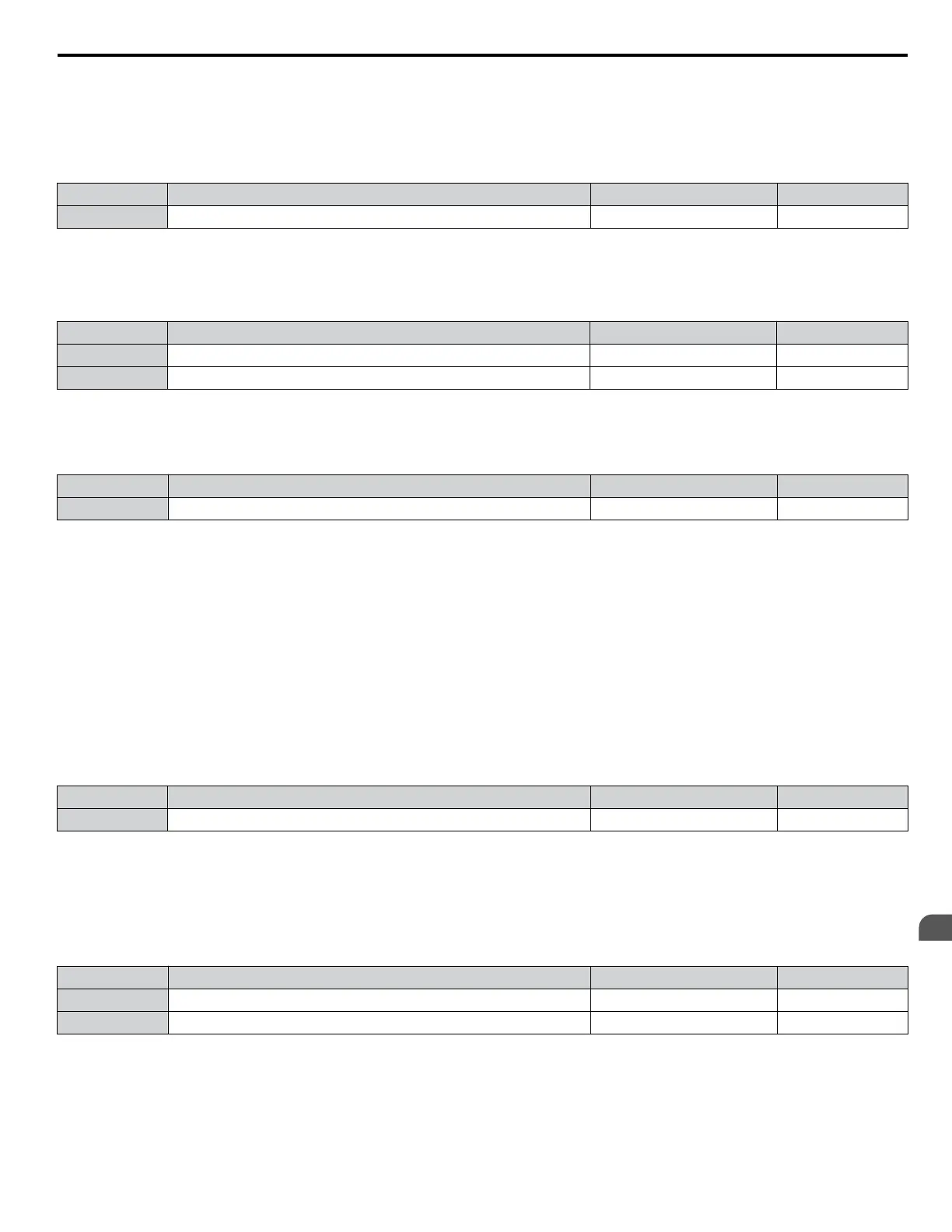
No. Name Setting Range Default
H3-06 Terminal A3 Function Selection 0 to 32 2
n
H3-07, H3-08: Terminal A3 Gain and Bias Setting
Parameter H3-07 sets the level of the selected input value that is equal to 10 Vdc input at terminal A3 (gain).
Parameter H3-08 sets the level of the selected input value that is equal to 0 V input at terminal A3 (bias).
No. Name Setting Range Default
H3-07 Terminal A3 Gain Setting -999.9 to 999.9% 100.0%
H3-08 Terminal A3 Bias Setting -999.9 to 999.9% 0.0%
n
H3-09:
Terminal A2 Signal Level Selection
Selects the input signal level for analog input A2. Set DIP switch S1 on the terminal board accordingly for a voltage input or
current input.
No. Name Setting Range Default
H3-09 Terminal A2 Signal Level Selection 0 to 3 2
Setting 0: 0 to 10 Vdc
The input level is 0 to 10 Vdc. Refer to Setting 0: 0 to 10 Vdc on page 155.
Setting 1: 0 to 10 Vdc Bipolar
The input level is -10 to 10 Vdc. Refer to Setting 1: -10 to 10 Vdc on page 155.
Setting 2: 4 to 20 mA
The input level is 4 to 20 mA. Negative input values by negative bias or gain settings will be limited to 0%.
Setting 3: 0 to 20 mA
The input level is 0 to 20 mA. Negative input values by negative bias or gain settings will be limited to 0%.
n
H3-10: Terminal A2 Function Selection
Determines the function assigned to analog input terminal A2.
No. Name Setting Range Default
H3-10 Terminal A2 Function Selection 0 to 32 0
n
H3-11, H3-12: Terminal A2 Gain and Bias Setting
Parameter H3-11 sets the level of the input value selected that is equal to 10 Vdc input or 20 mA input to terminal A2.
Parameter H3-12 sets the level of the input value selected that is equal to 0 V, 4 mA or 0 mA input at terminal A2.
Use
both parameters to adjust the characteristics of the analog input signal to terminal A2. The setting works in the same way
as parameters H3-03 and H3-04 for analog input A1.
No. Name Setting Range Default
H3-11 Terminal A2 Gain Setting -999.9 to 999.9% 100.0%
H3-12 Terminal A2 Bias Setting -999.9 to 999.9% 0.0%
n
H4-01, H4-04: Multi-Function Analog Output Terminal FM, AM Monitor Selection
Sets the desired drive monitor parameter Uo-oo to output as an analog value via terminal FM and AM. Refer to U1:
Operation Status Monitors on page 320 for a list of all monitors. The “Analog Output Level” column indicates whether a
monitor can be used for analog output.
Example: Enter “103” for U1-03.
4.6 Basic Drive Setup Adjustments
YASKAWA ELECTRIC TOEP C710616 41G YASKAWA AC Drive - A1000 Quick Start Guide
157
4
Start-Up Programming
& Operation

 Loading...


