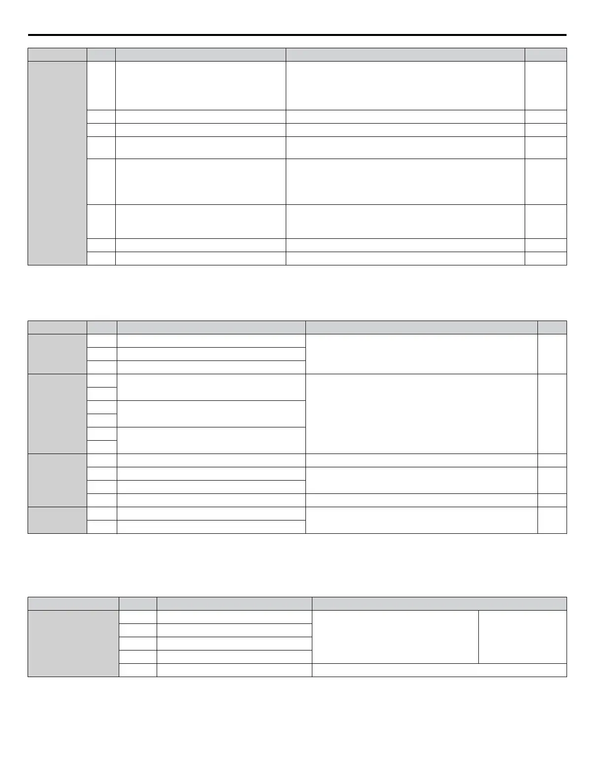
Type No. Terminal Name (Function) Function (Signal Level) Default Setting Page
Analog Inputs /
Pulse Train
Input
RP
Multi-function pulse train input
(Frequency reference)
• Input frequency range: 0 to 32 kHz
•
Signal Duty Cycle: 30 to 70%
• High level: 3.5 to 13.2 Vdc, low level: 0.0 to 0.8 Vdc
• Input impedance: 3 kΩ
138 298
+V Power supply for analog inputs 10.5 Vdc (max allowable current 20 mA) 136
-V Power supply for analog inputs -10.5 Vdc (max allowable current 20 mA) –
A1
Multi-function analog input 1
(Frequency reference bias)
-10 to 10 Vdc, 0 to 10 Vdc (input impedance: 20 kΩ) 136 155
A2
Multi-function analog input 2
(Frequency reference bias)
• -10 to 10 Vdc, 0 to 10 Vdc (input impedance: 20 kΩ)
• 4 to 20 mA, 0 to 20 mA (input impedance: 250 Ω)
• Voltage or current input must be selected by DIP switch S1 and
H3-09.
136 157
A3
Multi-function analog input 3
(Auxiliary frequency reference)/PTC Input
• -10 to 10 Vdc, 0 to 10 Vdc (input impedance: 20 kΩ)
• Use DIP switch S4 on the terminal board to select between analog
and PTC input.
136
AC Frequency reference common 0 V 136
E (G) Ground for shielded lines and option cards – –
n
Output Terminals
Table
3.8 lists the output terminals on the drive. Text in parenthesis indicates the default setting for each multi-function output.
Table 3.8 Control Circuit Output Terminals
Type No. Terminal Name (Function) Function (Signal Level) Default Setting Page
Fault Relay
Output
MA N.O. output (Fault)
30 Vdc, 10 mA to 1 A; 250 Vac, 10 mA to 1 A
Minimum load: 5 Vdc, 10 mA
153MB N.C. output (Fault)
MC Fault output common
Multi-Function
Digital Output
<1>
M1
Multi-function digital output (During run)
30 Vdc, 10 mA to 1 A; 250 Vac, 10 mA to 1 A
Minimum load: 5 Vdc, 10 mA
153
M2
M3
Multi-function digital output (Zero speed)
M4
M5
Multi-function digital output (Speed Agree 1)
M6
Monitor
Output
MP Pulse train output (Output frequency) 32 kHz (max) 298
FM Analog monitor output 1 (Output frequency)
-10 to +10 Vdc, 0 to +10 Vdc, or 4 to 20 mA. Refer
to Terminal
AM/FM Signal Selection on page 113 for details.
296
AM Analog monitor output 2 (Output current)
AC Monitor common 0 V –
Safety Monitor
Output
DM+ Safety monitor output
Outputs status of Safe Disable function. Closed when both Safe
Disable channels are closed. Up to +48 Vdc 50 mA
353
DM- Safety monitor output
<1> Refrain
from assigning functions to digital relay outputs that involve frequent switching, as doing so may shorten relay performance life. Switching
life is estimated at 200,000 times (assumes 1 A, resistive load).
n
Serial Communication Terminals
Table 3.9 Control Circuit Terminals: Serial Communications
Type No. Signal Name Function (Signal Level)
MEMOBUS/Modbus
Communication
<1>
R+ Communications input (+)
MEMOBUS/Modbus communication: Use an
RS-422 or RS-485 cable to connect the drive.
RS-422/RS-485
MEMOBUS/Modbus
communication
protocol
115.2 kbps (max.)
R- Communications input (-)
S+ Communications output (+)
S- Communications output (-)
IG Shield ground 0 V
<1> Enable
the termination resistor in the last drive in a MEMOBUS/Modbus network by setting DIP switch S2 to the ON position. Refer to the manual
section on Control I/O Connections for more information.
3.7 Control Circuit Wiring
106
YASKAWA ELECTRIC TOEP C710616 41G YASKAWA AC Drive - A1000 Quick Start Guide

 Loading...


