Setting Function Page
71 Speed/Torque Control Switch –
72 Zero Servo –
75 Up 2 Command
–
76 Down 2 Command
77 ASR Gain Switch –
78 External Torque Reference Polarity Inversion –
7A KEB Ride-Thru 2 (N.C.)
–
7B KEB Ride-Thru 2 (N.O.)
Setting Function Page
7C Short Circuit Braking (N.O.)
–
7D Short Circuit Braking (N.C.)
7E Forward/Reverse Detection –
7F PID Bi-directional Enable (No function) –
90 to 97 DriveWorksEZ Digital Input 1 to 8 –
9F DriveWorksEZ Disabled –
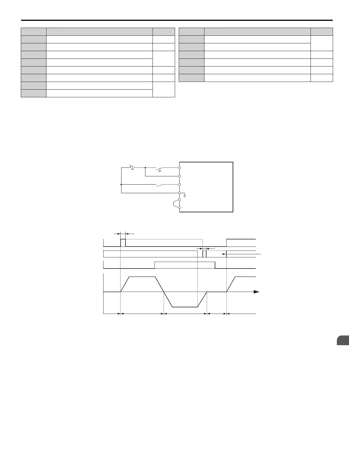
Setting 0: 3-Wire Sequence
The digital input programmed for 3-Wire control becomes the forward/reverse directional input, S1 becomes the Run command
input, and S2 becomes the Stop command input.
The drive starts the motor when the input S1 set for the Run command closes for longer than 2 ms. The drive stops the operation
when the Stop input S2 is released. When the digital input programmed for a forward/reverse operation is open, the drive is
set for forward operation. When the digital input is closed, the drive is set for reverse operation.
Note: Input the Run and Stop commands via S1 and S2 when selecting a 3-Wire sequence.
S1
S2
S5
SN
Run Command (Runs when Closed)
DRIVE
Stop Switch
(N.C.)
Run Switch
(N.O.)
Stop Command (Stops when Open)
FWD/REV (Multi-Function Input)
(H1-05 = 0)
Standard Digital Input Common
SC
SP
Figure 4.25 3-Wire Sequence Wiring Diagram
2 ms min.
Run command
Can be
ON or OFF
2 ms min.
ON (reverse)
ForwardpotSesreveRpotS
Can be either ON or OFF
OFF (forward)
Forward
Motor speed
Forward/reverse
command
Stop command
Figure 4.26 3-Wire Sequence
Note: 1. The Run command must be closed for more than 2 ms.
2. If
the Run command is active at power up and b1-17 = 0 (Run command at power up not accepted), the Run LED will flash to indicate
that protective functions are operating. If required by the application, set b1-17 to 1 to automatically issue the Run command upon drive
power up.
WARNING! Sudden Movement Hazard. Ensure start/stop and safety circuits are wired properly and in the correct state before applying
power to the drive. Failure to comply could result in death or serious injury from moving equipment.
WARNING! Sudden Movement Hazard. The drive may start unexpectedly in reverse direction after power up if it is wired for 3-Wire sequence
but set up for 2-Wire sequence (default). Make sure b1-17 is set to “0” (drive does not accept a Run command active at power up). When
initializing the drive use 3-Wire initialization. Failure to comply could result in death or serious injury from moving equipment.
n
H2-01 to H2-03: Terminal M1-M2, M3-M4, and M5-M6 Function Selection
The drive has three multi-function output terminals. Table 4.27 lists the functions available for theses terminals using H2-01,
H2-02, and H2-03.
4.6 Basic Drive Setup Adjustments
YASKAWA ELECTRIC TOEP C710616 41G YASKAWA AC Drive - A1000 Quick Start Guide
153
4
Start-Up Programming
& Operation

 Loading...


