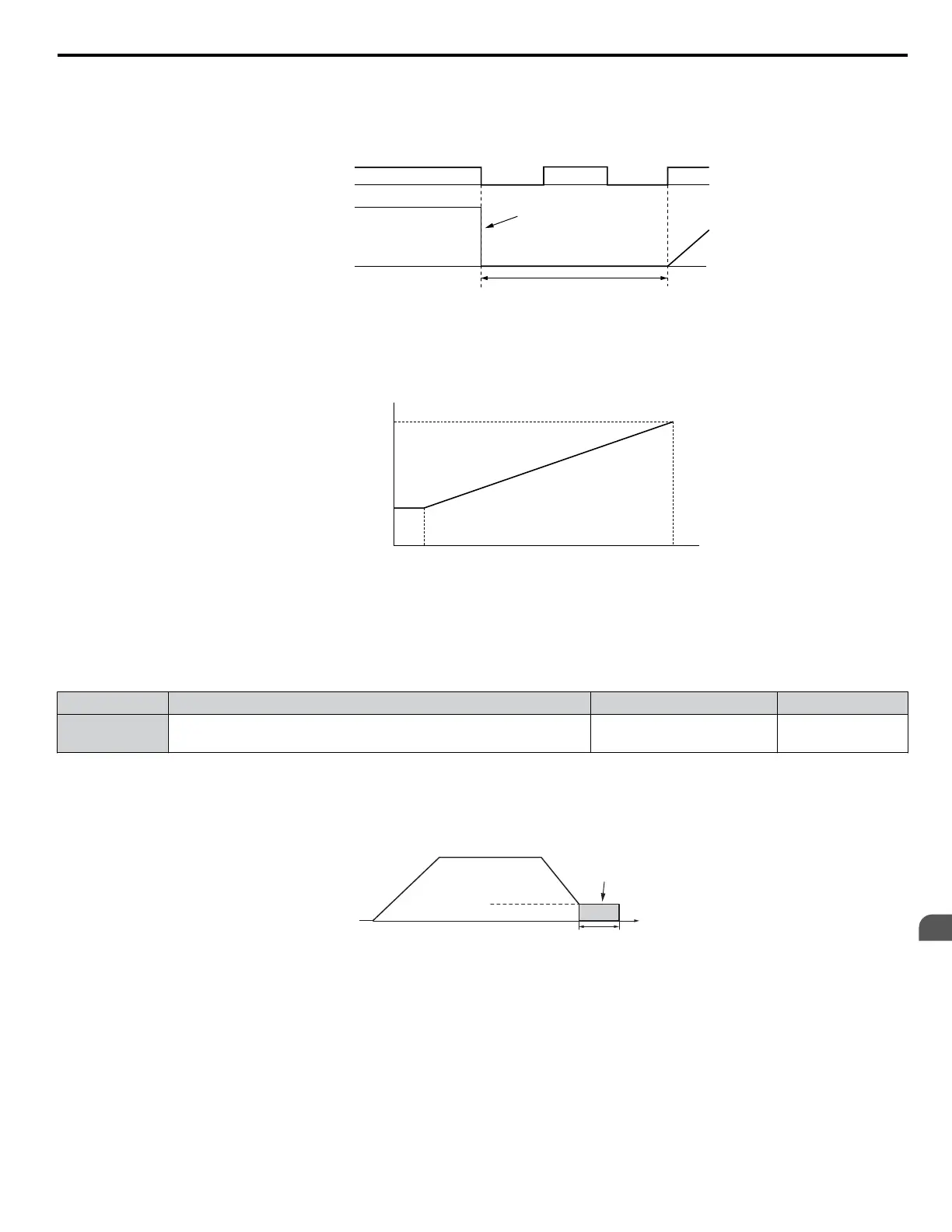
Setting 3: Coast to Stop with Timer
When the Run command is removed, the drive will turn off its output and the motor will coast to stop. The drive will not start
if a Run command is input before the time t (C1-02) has expired. Cycle the Run command that was activated during time t
after t has expired to start the drive.
Drive output shut off
Run wait time t
Run command
Output
frequency
ON ON ONOFF OFF
Figure 4.16 Coast to Stop with Timer
The wait time t is determined by the output frequency when the Run command is removed and by the active deceleration time.
Min output
frequency
100%
(Max output
frequency)
Output frequency
when Stop command
was entered
Run wait time t
Active deceleration time
Momentary Power Loss
Minimum Baseblock
Time (L2-03)
Figure 4.17 Run Wait Time Depending on Output Frequency
n
b2-01: DC Injection Braking Start Frequency
Active when “Ramp to Stop” is selected as the stopping method (b1-03 = 0).
No. Name Setting Range Default
b2-01 DC Injection Braking Start Frequency 0.0 to 10.0 Hz
Determined by
A1-02
The function triggered by parameter b2-01 depends on the control mode that has been selected.
V/f, V/f w/PG and OLV (A1-02 = 0, 1, 2)
For these control modes, parameter b2-01 sets the starting frequency for DC Injection Braking at Stop. When the output
frequency falls below the setting of b2-01, DC Injection Braking is enabled for the time set in parameter b2-04.
Output
Frequency
Time
b2-04
DC Injection
Braking
E1-09 Min. Output Freq.
b2-01 DC Inj. Braking Start Freq.
Figure 4.18 DC Injection Braking at Stop for V/f, V/f w/PG, and OLV
Note: If b2-01 is set to a smaller value than E1-09 (Minimum Frequency), then DC Injection Braking will begin when the frequency falls to the
E1-09 value.
OLV/PM and AOLV/PM (A1-02 = 5, 6)
For these control modes, parameter b2-01 sets the starting frequency for Short-Circuit Braking at Stop. When the output
frequency falls below the setting of b2-01, Short-Circuit Braking is enabled for the time set in parameter b2-13.
If
DC Injection Braking Time is enabled at stop, then DC Injection Braking is performed for the time set in b2-04 after Short-
Circuit Braking is complete.
4.6 Basic Drive Setup Adjustments
YASKAWA ELECTRIC TOEP C710616 41G YASKAWA AC Drive - A1000 Quick Start Guide
141
4
Start-Up Programming
& Operation

 Loading...


