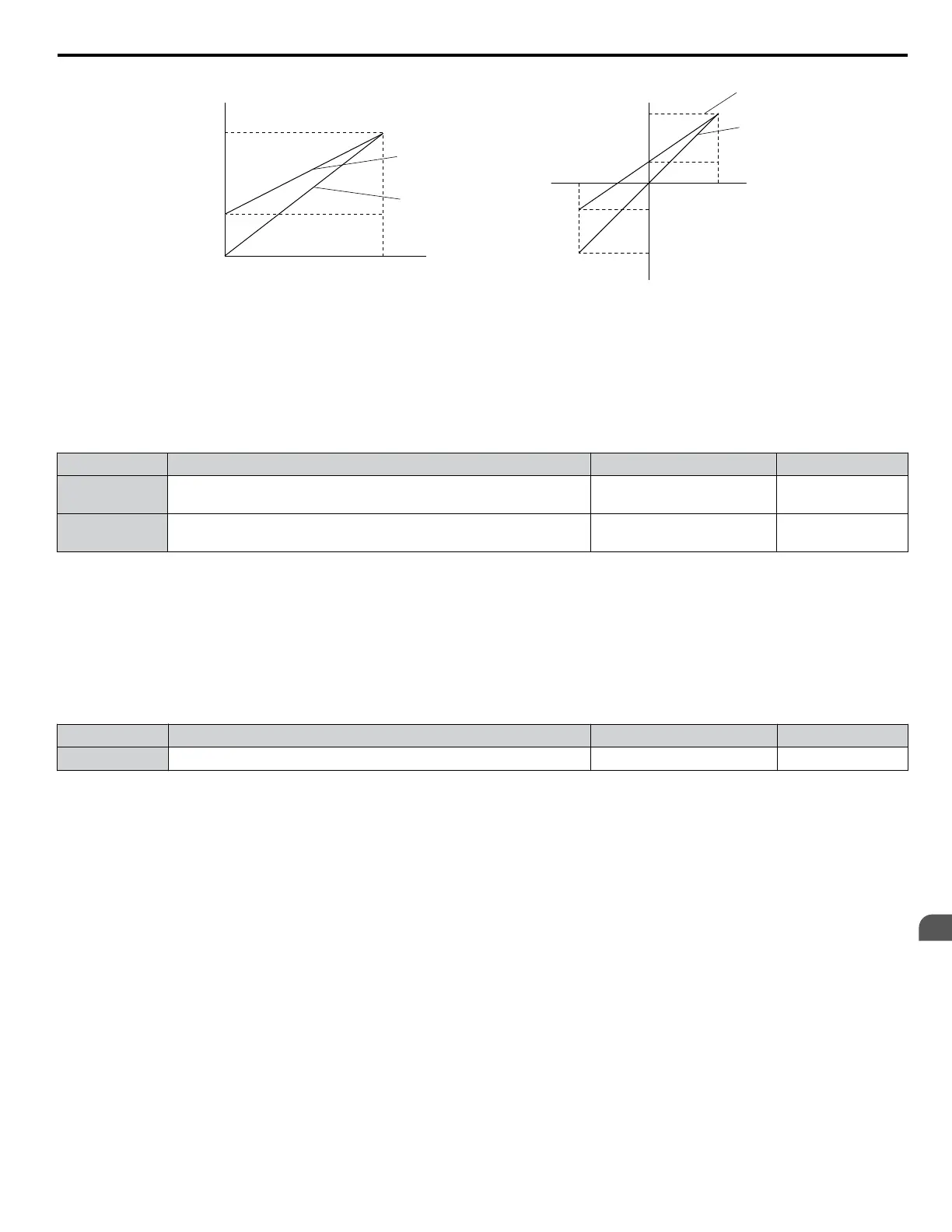
Gain = 100%
Bias = 30%
Gain = 100%
Bias = 0%
Gain 100%
Bias 30%
Gain 100%
Bias 0%
Monitor Value
Monitor Value
0 V
3 V
10 V
100%0%
Output Voltage
Output Voltage
H4-07, 08 = 0 H4-07, 08 = 1
10V
-10 V
100%
3 V
-4 V
-100%
Figure 4.32 Analog Output Gain and Bias Setting Example 3
n
H4-07, H4-08: Multi-Function Analog Output Terminal FM, AM Signal Level Selection
Sets the voltage output level of U parameter (monitor parameter) data to terminal FM and terminal AM using parameters
H4-07 and H4-08.
Set jumper S5 on the terminal board accordingly when changing these parameters. Refer to Terminal AM/FM Signal
Selection on page 113 for details on setting S5.
No. Name Setting Range Default
H4-07
Multi-Function Analog Output Terminal FM
Signal Level Selection
0 to 2 0
H4-08
Multi-Function Analog Output Terminal AM
Signal Level Selection
0 to 2 0
Setting 0: 0 to 10 V
Setting 1: -10 V to 10 V
Setting 2: 4 to 20 mA
n
L3-01: Stall Prevention Selection during Acceleration
Stall Prevention during acceleration prevents tripping with overcurrent (oC), motor overload (oL1), or drive overload (oL2)
faults common when accelerating with heavy loads.
L3-01 determines the type of Stall prevention the drive should use during acceleration.
No. Name Setting Range Default
L3-01 Stall Prevention Selection during Acceleration
0 to 2
<1>
1
<1> Setting 2 is not available for OLV/PM.
Setting 0: Disabled
No Stall Prevention is provided. If the acceleration time is too short, the drive may not be able to get the motor up to speed
fast enough, causing an overload fault.
Setting 1: Enabled
Enables Stall Prevention during acceleration. Operation varies depending on the control mode.
•
V/f Control, V/f Control with PG, and Open Loop Vector Control:
Acceleration is reduced when the output current value exceeds 85% of the level set to parameter L3-02 for a longer than the
time set to L3-27. The acceleration stops when the current exceeds L3-02. Acceleration continues when the current falls
below L3-02 for longer than the time set to L3-27.
The Stall Prevention level is automatically reduced in the constant power range. Refer to L3-03: Stall Prevention Limit
during Acceleration on page 161.
4.6 Basic Drive Setup Adjustments
YASKAWA ELECTRIC TOEP C710616 41G YASKAWA AC Drive - A1000 Quick Start Guide
159
4
Start-Up Programming
& Operation

 Loading...


