Digital Operator Display Fault Name
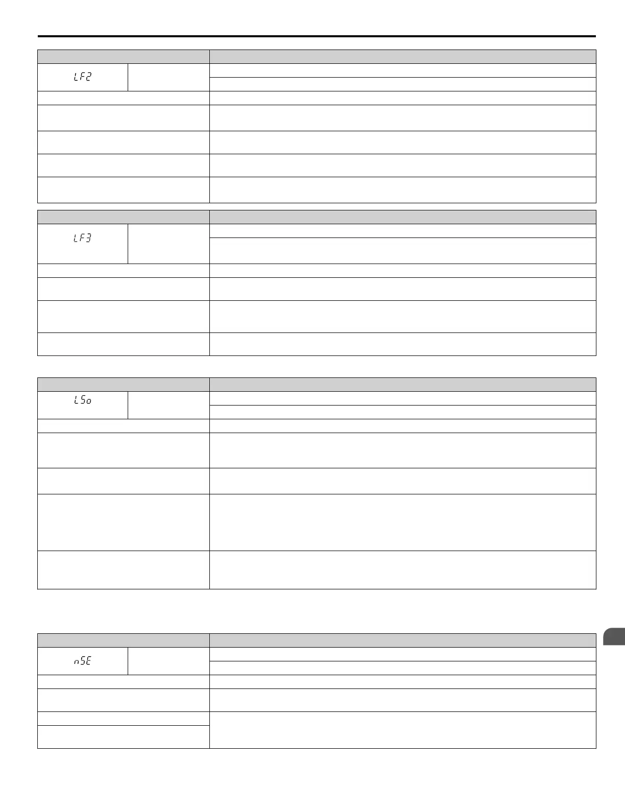
LF2
Output Current Imbalance
One or more of the phases in the output current are lost.
Cause Possible Solution
Phase loss has occurred on the output side of
the drive
• Check for faulty wiring or poor connections on the output side of the drive.
•
Correct the wiring.
Terminal wires are loose on the output side of
the drive
Apply the tightening torque specified in this manual to fasten the terminals. Refer to Main Circuit Wire
Gauges and Tightening Torques on page 94 for details.
The output circuit is damaged
If the problem continues, replace the control board or the entire drive. Contact Yaskawa or a Yaskawa
representative for instructions on replacing the control board.
Motor impedance or motor phases are uneven
• Measure the line-to-line resistance for each motor phase. Ensure all values match.
• Replace the motor.
Digital Operator Display Fault Name
<1>
LF3
Power Unit Output Phase Loss 3
• Phase loss occurred on the output side
•
Setting L8-78 to 1 enables Power Unit Output Phase Loss Protection
Cause Possible Solution
The gate drive board in the power unit is
damaged.
Cycle the power supply. If the fault continues to occur, replace the gate drive board or the drive. Contact
Yaskawa or a Yaskawa representative for instructions on replacing the gate drive board.
Cable to the current detection circuit in the
power unit is damaged or not connected
properly.
Check for incorrect wiring and correct any wiring mistakes.
Cable between the output rector and the power
unit is loose or not connected.
Contact Yaskawa or your nearest sales representative for instructions.
<1> Detected in models 4A0930 and 4A1200.
Digital Operator Display Fault Name
<1>
LSo
LSo Fault
Pull-out has been detected at low speed.
Cause Possible Solution
The incorrect motor code has been entered.
• Enter the correct motor code for the PM motor being used into E5-01.
•
For special-purpose motors, enter the correct data to all E5 parameters according to the test report
provided for the motor.
The load is too heavy.
• Reduce the load.
• Use a larger drive.
The drive incorrectly detected the position of
the motor poles.
• Make sure some external force is not rotating the motor at start.
• Enable Speed Search Selection at start. (b3-01 = 1).
• If the value displayed in U6-57 is lower than 819, then set the polarity judge current (n8-84) higher
than the default value. If the motor is to be operated at a speed higher than the rated speed, consult with
the manufacturer.
Values set to parameters L8-93, L8-94, and
L8-95 are incorrect.
• Increase the value set to L8-93.
• Increase the value set to L8-94.
• Increase the value set to L8-95.
<1> This function prevents continuous operation in reverse when using high frequency injection (n8-57 = 1) in AOLV/PM (A1-02 = 6) with a motor
for
which no motor code has been entered (it does not only prevent reverse operation). Set L8-93, L8-94, and L8-95 to low values within range of
erroneous detection to quickly detect undesirable reverse operation.
Digital Operator Display Fault Name
nSE
Node Setup Error
A terminal assigned to the node setup function closed during run.
Cause Possible Solution
Overcurrent occurred during Overexcitation
Deceleration.
Reduce the overexcitation deceleration gain (n3–13).
The node setup terminal closed during run.
Stop the drive when using the node setup function.
A Run command was issued while the node
setup function was active.
5.2 Fault Detection
YASKAWA ELECTRIC TOEP C710616 41G YASKAWA AC Drive - A1000 Quick Start Guide
185
5
Troubleshooting

 Loading...


