Digital Operator Display Fault Name
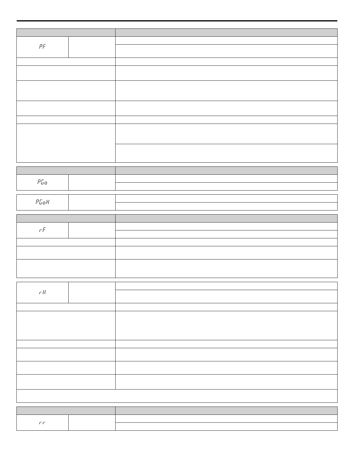
PF
Input Phase Loss
Drive input power has an open phase or has a large imbalance of voltage between phases. Detected when
L8-05 is set 1 (enabled).
Cause Possible Solution
There is phase loss in the drive input power
• Check for wiring errors in the main circuit drive input power.
•
Correct the wiring.
There is loose wiring in the drive input power
terminals
• Ensure the terminals are tightened properly.
• Apply the tightening torque as specified in this manual. Refer to Main Circuit Wire Gauges and
Tightening Torques on page 94 for details.
There is excessive fluctuation in the drive
input power voltage
• Check the voltage from the drive input power.
• Review the possible solutions for stabilizing the drive input power.
There is poor balance between voltage phases Stabilize drive input power or disable phase loss detection.
The main circuit capacitors are worn
• Check the maintenance time for the capacitors (U4-05).
• Replace the main capacitor(s) if U4-05 is greater than 90%. For instructions on replacing the
capacitor(s), contact Yaskawa or a Yaskawa representative.
Check for problems with the drive input power. If drive input power appears normal but the alarm
continues to occur, replace either the control board or the entire drive. For instructions on replacing the
control board, contact Yaskawa or a Yaskawa representative.
Digital Operator Display Fault Name
PGo
PG Disconnect (for any control modes using a PG option card)
No PG pulses are received for longer than the time set to F1-14.
PGoH
PG Hardware Fault (detected when using a PG-X3 option card)
PG cable is not connected properly.
Digital Operator Display Fault Name
rF
Braking Resistor Fault
The resistance of the braking resistor is too low.
Cause Possible Solution
The proper braking resistor option has not
been installed
Select a braking resistor option that it fits the drive braking transistor specification.
A regenerative converter, regenerative unit, or
braking unit is being used and the ⊕1 or ⊕3
terminal is connected to ⊖ terminal
Set L8-55 to 0 to disable the braking transistor protection selection.
rH
Braking Resistor Overheat
Braking resistor protection was triggered.
Fault detection is enabled when L8-01 = 1 (disabled as a default).
Cause Possible Solution
Deceleration time is too short and excessive
regenerative energy is flowing back into the
drive
• Check the load, deceleration time, and speed.
•
Reduce the load inertia.
• Increase the deceleration times (C1-01 to C1-08).
• Replace the dynamic braking option with a larger device that can handle the power that is discharged.
The duty cycle is too high Check the duty cycle. Maximum of 3% duty cycle is available when L8-01 = 1.
Excessive braking inertia
Recalculate braking load and braking power. Reduce the braking load by adjusting braking resistor
settings.
The braking operation duty cycle is too high
Check the braking operation duty cycle. Braking resistor protection for ERF-type braking resistors
(L8-01 = 1) allows a braking duty cycle of maximum 3%.
The proper braking resistor has not been
installed
• Check the specifications and conditions for the braking resistor device.
• Select the optimal braking resistor.
Note: The magnitude of the braking load trips the braking resistor overheat alarm, NOT the surface temperature. Using the braking resistor more
frequently than its rating permits will trip the alarm even when the braking resistor surface is not very hot.
Digital Operator Display Fault Name
rr
Dynamic Braking Transistor
The built-in dynamic braking transistor failed.
5.2 Fault Detection
192
YASKAWA ELECTRIC TOEP C710616 41G YASKAWA AC Drive - A1000 Quick Start Guide

 Loading...


