No.
(Addr.
Hex)
Name Description
Analog
Output Level
Unit
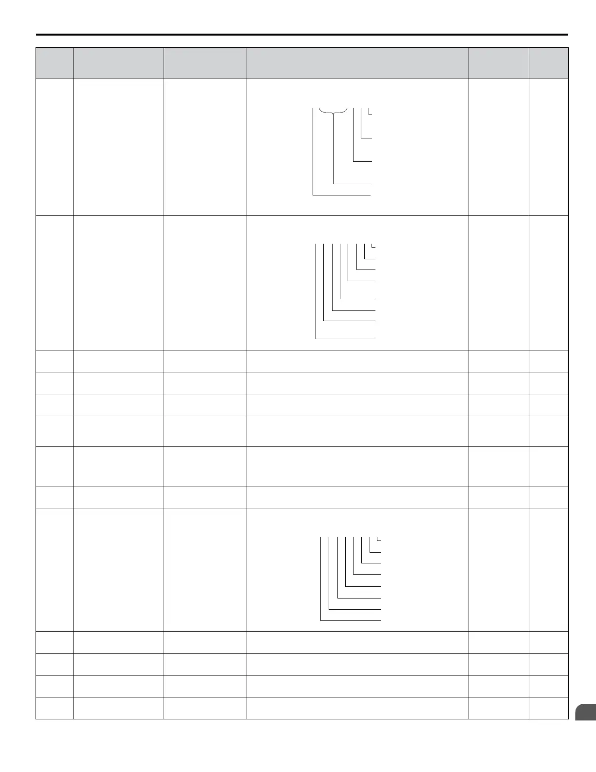
U1-11
(004A)
Output Terminal Status Output Term Sts
Displays the output terminal status.
U1
-
11=
00000000
Multi-Function
Digital Output
(terminal M1-M2)
Digital Output
(terminal M3-M4)
Digital Output
(terminal M5-M6)
Multi-Function
Multi-Function
Not Used
Fault Relay
(terminal MA-MC closed
MA-MC open)
1
1
1
1
0
No signal
output available
–
U1-12
(004B)
Drive Status Int Ctl Sts 1
Displays the drive operation status.
U1
-
12=
00000000
During run
During zero-speed
During REV
During fault reset
signal input
During speed agree
Drive ready
During alarm
detection
During fault detection
1
1
1
1
1
1
1
1
No signal
output available
–
U1-13
(004E)
Terminal A1 Input Level Term A1 Level
Displays the signal level to analog input terminal A1. 10 V: 100%
(-10 to +10 V)
0.1%
U1-14
(004F)
Terminal A2 Input Level Term A2 Level
Displays the signal level to analog input terminal A2. 10 V: 100%
(-10 to +10 V)
0.1%
U1-15
(0050)
Terminal A3 Input Level Term A3 Level
Displays the signal level to analog input terminal A3. 10 V: 100%
(-10 to +10 V)
0.1%
U1-16
(0053)
Output Frequency after
Soft Starter
SFS Output
Displays output frequency with ramp time and S-curves. Units
determined by o1-03.
10 V: Max
frequency
(-10 to +10 V)
0.01 Hz
U1-17
(0058)
DI-A3 Input Status DI Opt Status
Displays the reference value input from the DI-A3 option card.
Display
will appear in hexadecimal as determined by the digital
card input selection in F3-01.
3FFFF: Set (1 bit) + sign (1 bit) + 16 bit
No signal
output available
–
U1-18
(0061)
oPE Fault Parameter OPE Error Code
Displays the parameter number that caused the oPE02 or oPE08
operation error.
No signal
output available
–
U1-19
(0066)
MEMOBUS/Modbus
Error Code
Transmit Err
Displays the contents of a MEMOBUS/Modbus error.
U1
-
19=
00000000
CRC Error
Data Length Error
Not Used
Parity Error
Overrun Error
Framing Error
Timed Out
Not Used
1
1
0
1
1
1
1
0
No signal
output available
–
U1-21
(0077)
AI-A3 Terminal V1
Input Voltage Monitor
AI Opt Ch1 Level
Displays the input voltage to terminal V1 on analog input card
AI-A3.
10 V: 100%
(-10 to +10 V)
0.1%
U1-22
(072A)
AI-A3 Terminal V2
Input Voltage Monitor
AI Opt Ch2 Level
Displays the input voltage to terminal V2 on analog input card
AI-A3.
10 V: 100%
(-10 to +10 V)
0.1%
U1-23
(072B)
AI-A3 Terminal V3
Input Voltage Monitor
AI Opt Ch3 Level
Displays the input voltage to terminal V3 on analog input card
AI-A3.
10 V: 100%
(-10 to +10 V)
0.1%
U1-24
(007D)
Input Pulse Monitor Term RP Inp Freq
Displays the frequency to pulse train input terminal RP. Determined by
H6-02
1 Hz
B.13 U: Monitors
YASKAWA ELECTRIC TOEP C710616 41G YASKAWA AC Drive - A1000 Quick Start Guide
321
B
Parameter List

 Loading...


