2.14 Control Circuit Wiring
106 YASKAWA SIEPC71061723A YASKAWA AC Drive CR700 Technical Manual
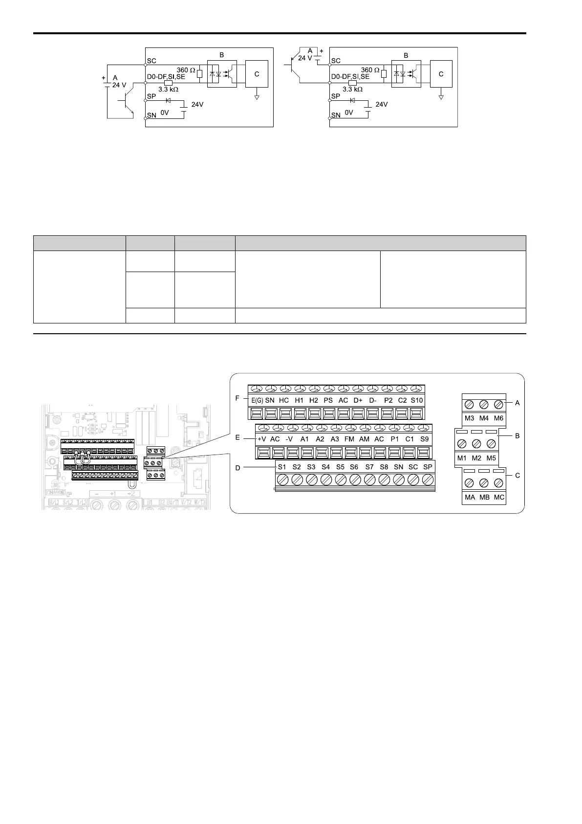
A - External power supply
B - Photocoupler
C - Signal processor
Figure 2.108 Wiring Digital Input Option (DI-A3)
■ Serial Communication Terminals
Refer to
Table 2.20 for a list of serial communication terminals and functions.
Table 2.20 Serial Communication Terminals
Type Terminal Terminal Name Function (Signal Level)
Modbus Communication
D+
Communication
input/output (+)
MEMOBUS/Modbus communications
Use an RS-485 cable to connect the drive.
Note:
Set DIP switch S2 to ON to enable the
termination resistor in the last drive in a
MEMOBUS/Modbus network.
• RS-485
• MEMOBUS/Modbus communication protocol
• Maximum 115.2 kbps
D-
Communication
output (-)
AC Shield ground
0 V
◆ Terminal Configuration
Control circuit terminals should are arranged as shown in the following figure.
A - Terminal block (TB2-3)
B - Terminal block (TB2-2)
C - Terminal block (TB2-1)
D - Terminal block (TB1)
E - Terminal block (TB3)
F - Terminal block (TB4)
Figure 2.109 Control Circuit Terminal Arrangement
The tightening torque for terminals is displayed on the reverse side of the front cover.

 Loading...


