5.3 MEMOBUS/Modbus Communications
304 YASKAWA SIEPC71061723A YASKAWA AC Drive CR700 Technical Manual
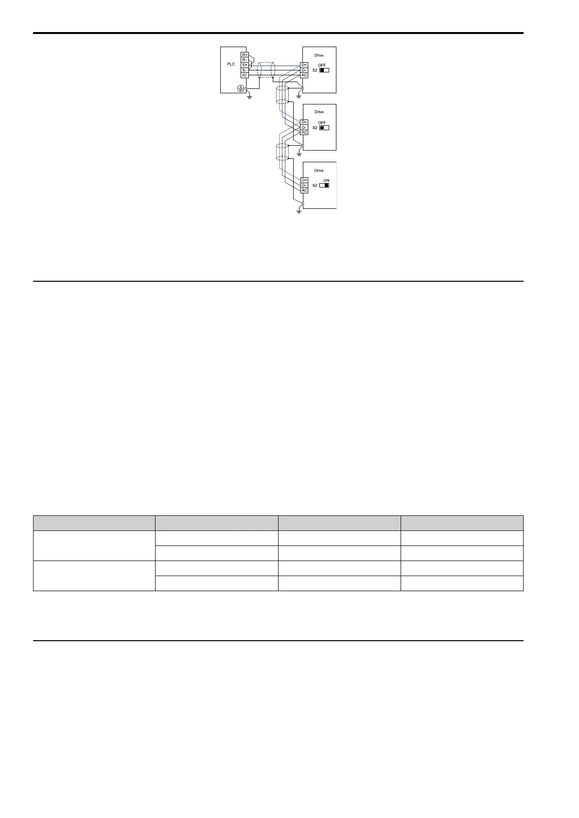
Figure 5.4 Wiring Diagram for More than One Drive
Note:
Set DIP switch S2 to the ON position on the last drive of the MEMOBUS/Modbus communication network to enable the termination
resistor.
◆ Drive Operations by MEMOBUS/Modbus
The drive parameters apply to the settings even if the drive is run during MEMOBUS/Modbus communications.
This section describes the types of usable functions and their related parameters.
■ Executable Function
A PLC can perform the following operations with MEMOBUS/Modbus communications at any time regardless of
parameter settings (except for H5-xx).
• Observe the drive status and operate the drive from a PLC
• Set and view parameters
• Fault Reset Procedure
• Multi-function input setting (The input command from MEMOBUS/Modbus communications and MFDI
terminals (S1 to S10) are linked by a logical OR operation.)
■ Drive Control
Select the external command for setting the frequency references and the motor run/stop using MEMOBUS/
Modbus communications, and set the parameters according to the application using the following table.
Table 5.2 Required Parameter Setting for Drive Control from MEMOBUS/Modbus
LOCAL Control Selected No. Name Setting Value
External reference 1
b1-01 Frequency Reference Selection 1 2 [Memobus/Modbus Communications]
b1-02 Run Command Selection 1 2 [Memobus/Modbus Communications]
External reference 2
b1-15 Frequency Reference Selection 2 2 [Memobus/Modbus Communications]
b1-16 Run Command Selection 2 2 [Memobus/Modbus Communications]
For more information about operation mode selection, refer to b1-01 [Frequency Reference Selection 1] and b1-02
[Run Command Selection 1]. Refer to H1-xx = 2 [MFDI Function Selection = External Reference 1/2 Selection]
for more information about external command.
◆ Communications Timing
To prevent overrun of the slave side, the master cannot send a message to the same drive for a certain amount of
time. Similarly, to prevent overrun of the master side, the slave cannot send a response message to the master for a
certain amount of time. This section explains the message send/receive timing.
■ Command Message from Master to Slave
To prevent data loss and overrun, after the master receives a message from the slave, the master cannot send the
same type of command message to the same slave for a certain amount of time. The minimum wait time differs
depending on the type of message. Check by referencing the following table.

 Loading...


