Startup Procedure and Test Run
3
3.10 Crane Application Setup Procedure
YASKAWA SIEPC71061723A YASKAWA AC Drive CR700 Technical Manual 215
■ S6-01 and S6-04 Settings
Setting
Value
Detection Conditions
Type Operation after Detection Drive Recovery
Enabled Disabled
During
Run
During
speed
agree
ment
0 - x - - - - -
1 x - - x
Alarm Alarm Only
When the Run command is OFF and
the motor has stopped, the drive will
return to the state before the fault was
triggered.
*1
2 x - x -
3 x - - x
Fault
(Triggers a fault relay
output)
Coast to Stop
Push on the keypad or turn ON
the terminal set for “Fault Reset” to
reset the fault.
4 x - x -
5 x - - x
Alarm Alarm Only
When the Run command is OFF and
the motor has stopped, the drive will
return to the state before the fault was
triggered.
*1
6 x - x -
*1 Pushing on the keypad will not reset an alarm.
■ Multi-Function Digital Output
The following table shows the ON/OFF conditions of the MFDO terminals.
H2-xx
Setting Value
Name Description
0B Torque Detection 1 (N.O.)
If the drive detects overtorque based on the conditions set for Overtorque Detection 1, then this
digital output will switch ON.
The digital output will switch OFF when oL3 is cleared from the keypad display.
17 Torque Detection 1 (N.C.)
If the drive detects overtorque based on the conditions set for Overtorque Detection 1, then this
digital output will switch OFF.
The digital output will switch ON when oL3 is cleared from the keypad display.
18 Torque Detection 2 (N.O.)
If the drive detects overtorque based on the conditions set for Overtorque Detection 2, then this
digital output will switch ON.
The digital output will switch OFF when oL4 is cleared from the keypad display.
19 Torque Detection 2 (N.C.)
If the drive detects overtorque based on the conditions set for Overtorque Detection 2, then this
digital output will switch OFF.
The digital output will switch ON when oL4 is cleared from the keypad display.
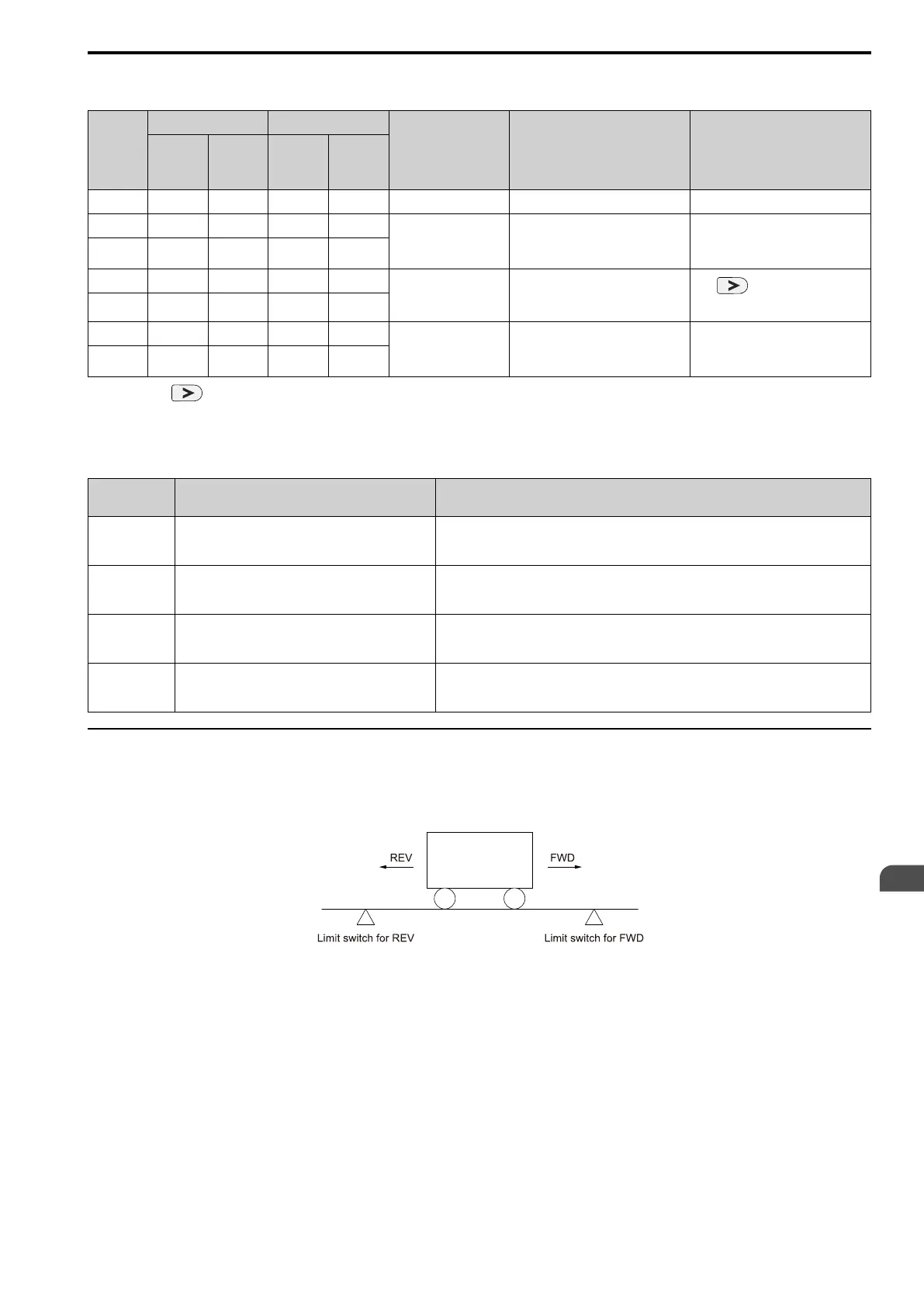
◆ Travel Limit Function
The Travel Limit function is a limit switch used to prevent over-travel by the transport cart and over-hoist in a
hoist application. You can set the MFDI terminals for FWD/REV and N.O./N.C. switching.
Note:
If the Run command on the forward side is disabled, then by triggering an input terminal set for the Travel Limit, the drive will show
FWdL [Fwd Limit (FWdL)] on the keypad. If the Run command on the reverse side is disabled, the drive will show rEvL [Rev Limit
(rEvL)] on the keypad.
■ Multi-Funciton Digital Input
The following table shows the MFDI terminal operation after Travel Limit Detection.

 Loading...


