2.9 Change the Drive Enclosure Type
58 YASKAWA SIEPC71061723A YASKAWA AC Drive CR700 Technical Manual
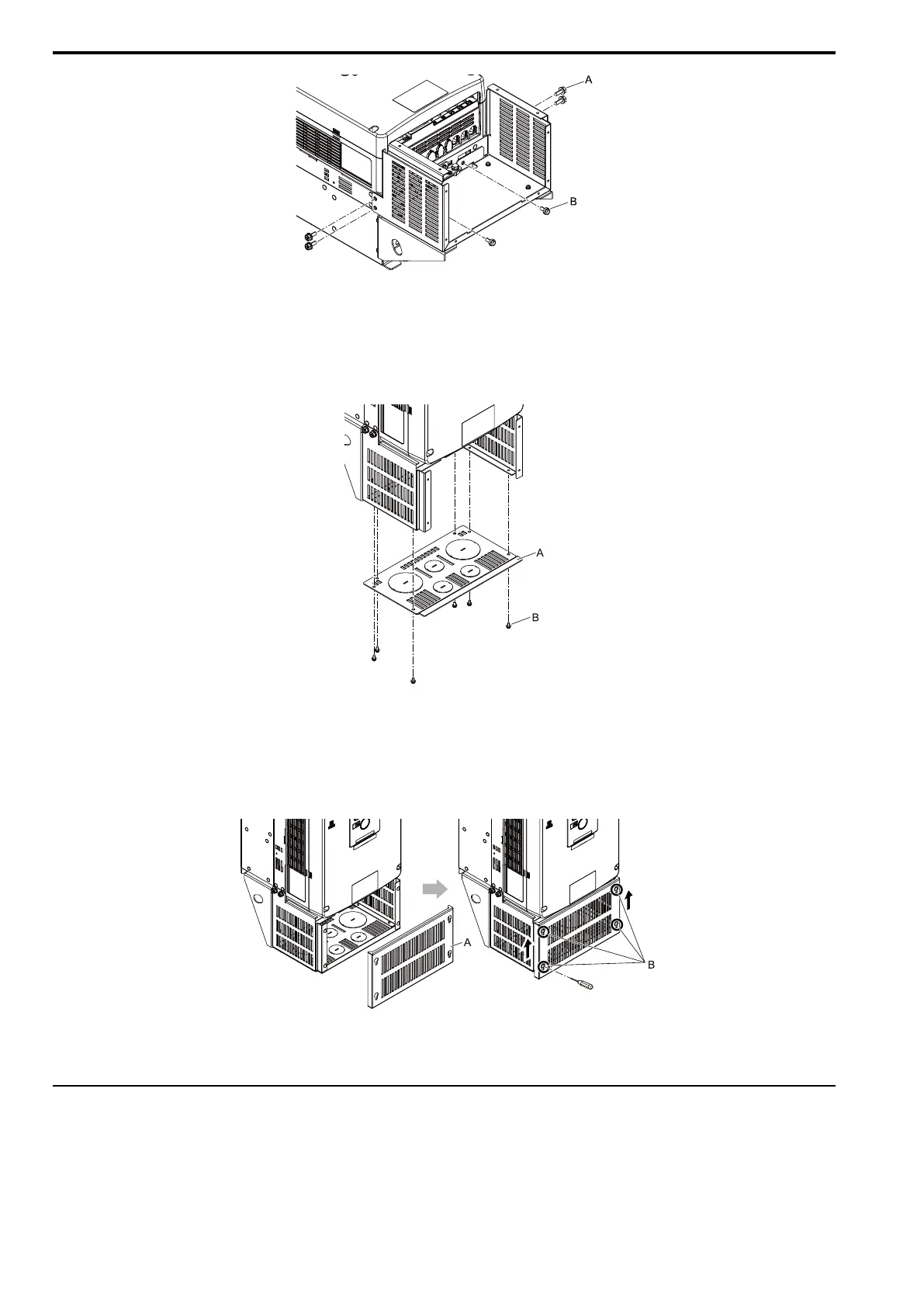
A - M6 × 16 upset head bolts B - M6 × 14 pan head screws
Figure 2.49 Safety the Base
4. Use the included screws to install the UL Type 1 conduit bracket to the base.
Tighten the screws to a correct tightening torque:
• 0.98 N∙m to 1.33 N∙m (8.67 lbf∙in to 11.77 lbf∙in)
A - Conduit bracket B - M4 × 8 pan head screws
Figure 2.50 Install the Conduit Bracket
5. Use the included screws to install the front cover to the base.
While slightly lifting the front cover, tighten the screws to a correct tightening torque:
• 0.98 N∙m to 1.33 N∙m (8.67 lbf∙in to 11.77 lbf∙in)
A - Front cover B - M4 × 10 truss head screws
Figure 2.51 Install the Front Cover
◆ Attach the Protective Cover (Procedure E)
■ Install the Top Protective Cover
Put the hooks on the back of the top protective cover into the hook holes on the top of the drive.
Move the top protective cover forward to align the screw holes.
Tighten the screws to a correct tightening torque:

 Loading...


