11.8 H: Terminal Functions
724 YASKAWA SIEPC71061723A YASKAWA AC Drive CR700 Technical Manual
◆ H3: Analog Inputs
WARNING! Sudden Movement Hazard. Do test runs and examine the drive to make sure that the command references are
correct. If you set the command reference incorrectly, it can cause damage to the drive or serious injury or death.
Drives have three analog input terminals, named terminals A1, A2, and A3. H3 parameters select the functions set
to these analog input terminals and adjust signal levels.
The table shows the functions that you can set to analog input terminals. Use H3-02, H3-06, and H3-10 [MFAI
Function Select] to set functions.
Table 11.32 Multi-Function Analog Input Terminal Settings
Setting Value Function
0 Frequency Reference
1 Frequency Gain
2 Auxiliary Frequency Reference 1
3 Auxiliary Frequency Reference 2
4 Output Voltage Bias
5 Accel/Decel Time Gain
6 DC Injection Braking Current
7 Torque Detection Level
8 Stall Prevent Level during Run
C Overload Detection Level
Setting Value Function
D Frequency Bias
E Motor Temperature (PTC Input)
F Not Used
10 Forward Torque Limit
11 Reverse Torque Limit
12 Regenerative Torque Limit
14 Torque Compensation
15 General Torque Limit
1F Not Used
Note:
All analog input scaling uses gain and bias for adjustment. Set the gain and bias values correctly.
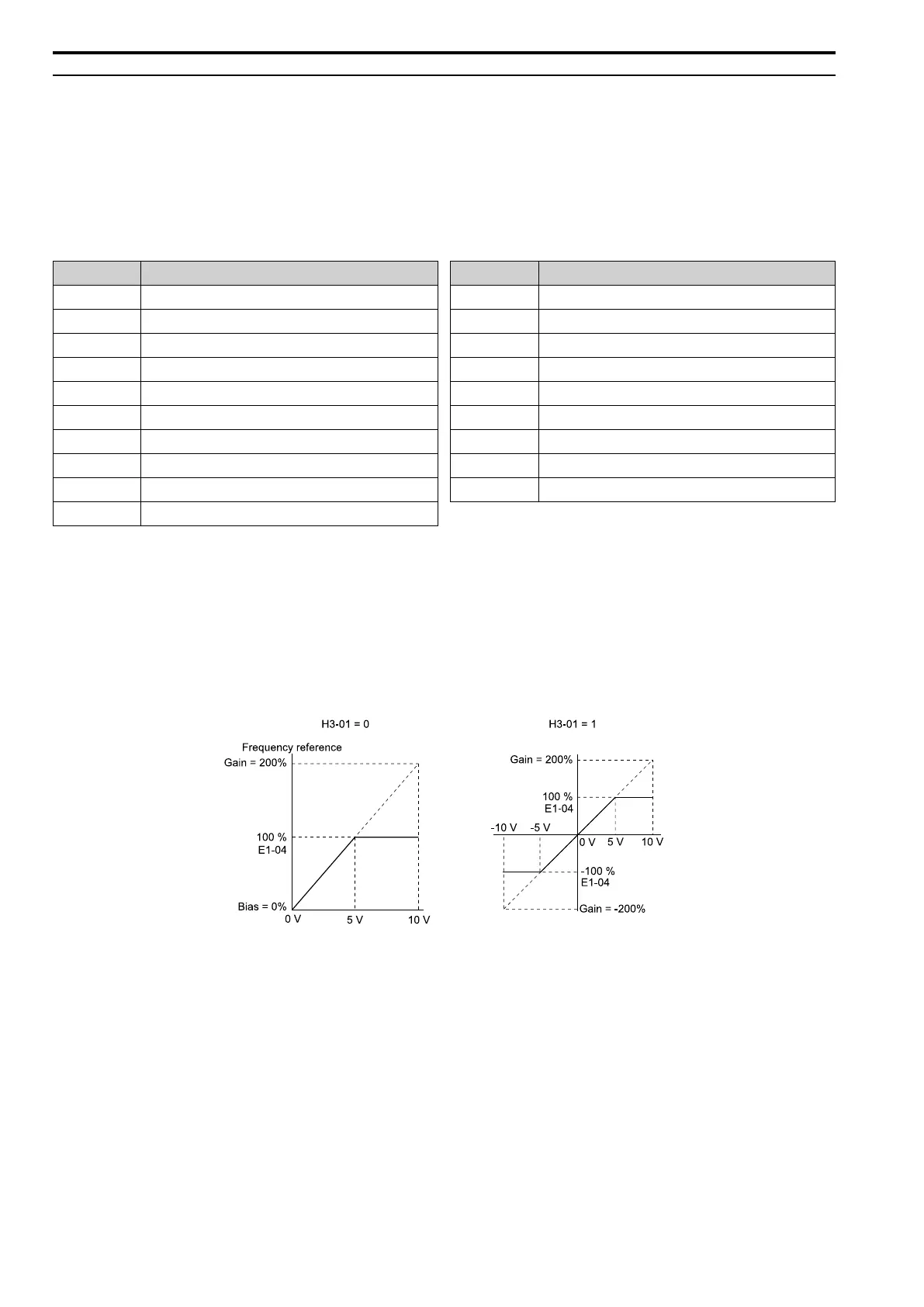
■ Example Analog Input Settings
• The function set for terminal A1 is set with Frequency Reference [H3-02 = 0], the gain is 200% [H3-03 =
200.0], and the bias is 0% [H3-04 = 0.0].
When you input a 10 V signal, the frequency reference will be 200%.
When you input a 5 V signal, the frequency reference will be 100%. As the drive output at this time is restricted
by E1-04 [Maximum Output Frequency], the frequency reference will be at 100% when a signal of 5 Vor more
is input.
Figure 11.71 Freq Reference When the Analog Input Gain Setting Is Adjusted
• The function set for terminal A1 is set with Frequency Reference [H3-02 = 0], the gain is 100% [H3-03 =
100.0], and the bias is -25% [H3-04 = -25.0].
When you input a 0 V signal, the frequency reference will be -25%.
When H3-01 = 0 [Terminal A1 Signal Level Select = 0 to 10V (Lower Limit at 0)], when you input a 0 V to 2 V
signal, the frequency reference will be 0%. When you input a 2 V to 10 V signal, the frequency reference will
be 0% to 100%.
When H3-01 = 1 [-10 to +10V (Bipolar Reference)], it enables signals of positive and negative polarities. When
you input a 0 V to 2 V signal, and the motor rotates in reverse.

 Loading...


