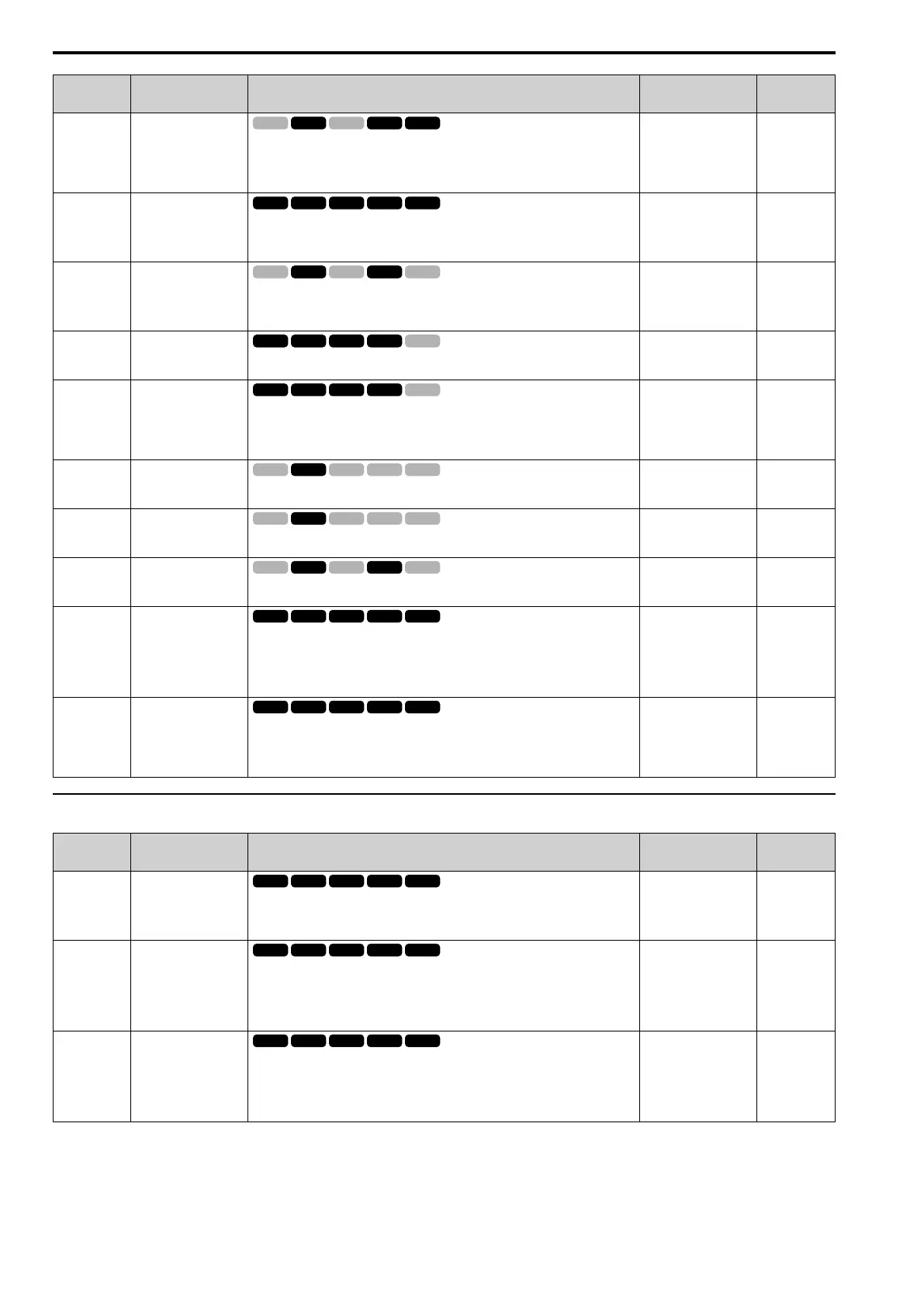
10.9 F: Options
488 YASKAWA SIEPC71061723A YASKAWA AC Drive CR700 Technical Manual
No.
(Hex.)
Name Description
Default
(Range)
Ref.
F1-20
(03B4)
Encoder 1 PCB
Disconnect Detect
Sets the function that enables and disables detection of a disconnected PG-X3 encoder
connection cable. Detects PGoH [Encoder (PG) Hardware Fault] when F1-20 = 1.
0 : Disable
1 : Enabled
1
(0, 1)
655
F1-21
(03BC)
Encoder 1 Signal
Selection
Sets the number of channels for the signal to the encoder option.
0 : A Pulse Detection
1 : AB Pulse Detection
0
(0, 1)
655
F1-30
(03AA)
Motor 2 Encoder PCB
Port Select
Sets the connector used when the motor 2 encoder option is installed in the drive.
0 : CN5-C
1 : CN5-B
1
(0, 1)
655
F1-31
(03B0)
Encoder 2 Pulse Count
(PPR)
Sets the number of output pulses per revolution of the encoder. This parameter is for
motor 2.
1024
(1 - 60000 ppr)
655
F1-32
(03B1)
Encoder 2 Rotation
Selection
Sets the output sequence for the A and B pulses from the encoder, assuming that the
motor is operating in the forward direction. This parameter is for motor 2.
0 : Pulse A leads in FWD Direction
1 : Pulse B leads in FWD Direction
0
(0, 1)
655
F1-33
(03B2)
Encoder 2 Gear Teeth 1
Sets the number of gear teeth on the motor side for motor 2. This parameter and F1-34
[Encoder 2 Gear Teeth 2] set the gear ratio between the motor and encoder.
0
(0 - 1000)
655
F1-34
(03B3)
Encoder 2 Gear Teeth 2
Sets the number of gear teeth on the load side for motor 2. This parameter and F1-33
[Encoder 2 Gear Teeth 1] set the gear ratio between the motor and encoder.
0
(0 - 1000)
656
F1-35
(03BE)
Encoder 2 Pulse Monitor
Scaling
Sets the dividing ratio for monitor signals output from the encoder option. This
parameter is for motor 2.
001
(001 - 032, 102 - 132 (1 -
1/32))
656
F1-36
(03B5)
Encoder 2 PCB
Disconnect Detect
Sets the function that enables and disables detection of a disconnected PG-X3 encoder
connection cable. PGoH [Encoder (PG) Hardware Fault] is detected when this
parameter is enabled. This parameter is for motor 2.
0 : Disable
1 : Enabled
1
(0, 1)
656
F1-37
(03BD)
Encoder 2 Signal
Selection
Sets the number of channels for the signal to the encoder option. This parameter is for
motor 2.
0 : A Pulse Detection
1 : AB Pulse Detection
0
(0, 1)
656
◆ F2: Analog Input Option
No.
(Hex.)
Name Description
Default
(Range)
Ref.
F2-01
(038F)
Analog Input Function
Selection
Sets the input method for the analog reference used with AI-A3.
0 : 3 Independent Channels
1 : 3 Channels Added Together
0
(0, 1)
657
F2-02
(0368)
RUN
Analog Input Option
Card Gain
Sets the analog reference gain as a percentage when the maximum output frequency is
100%.
Note:
Set F2-01 = 1 [Analog Input Function Selection = 3 Channels Added Together] to
enable this function.
100.0%
(-999.9 - +999.9%)
658
F2-03
(0369)
RUN
Analog Input Option
Card Bias
Sets the analog reference bias as a percentage when the maximum output frequency is
100%.
Note:
Set F2-01 = 1 [Analog Input Function Selection = 3 Channels Added Together] to
enable this function.
0.0%
(-999.9 - +999.9%)
658

 Loading...


