Parameter Details
11
11.7 F: Options
YASKAWA SIEPC71061723A YASKAWA AC Drive CR700 Technical Manual 657
■ F2-01: Analog Input Function Selection
No.
(Hex.)
Name Description
Default
(Range)
F2-01
(038F)
Analog Input Function
Selection
Sets the input method for the analog reference used with AI-A3.
0
(0, 1)
Note:
When the AI-A3 card is not mounted in the drive, analog input terminals A1 to A3 on the drive are always enabled. The setting of this
parameter does not have an effect.
0 : 3 Independent Channels
Set F2-01 = 0 to increase the precision of A/D conversion when you use the functions for terminals A1 to A3 on
the drive as they are. You can input the MFAI signal from terminals V1 through V3 for AI-A3. The functions for
terminals A1, A2, and A3 on the drive are sent to terminals V1, V2, and V3 for AI-A3. Use gain and bias
adjustment when you input current to set signals to have negative numbers.
Note:
• Set b1-01 = 1 [Frequency Reference Selection 1 = Analog Input] to set inputs individually.
• If F2-01 = 0 and b1-01 = 3 [Option PCB], the drive will detect oPE05 [Run Cmd/Freq Ref Source Sel Err].
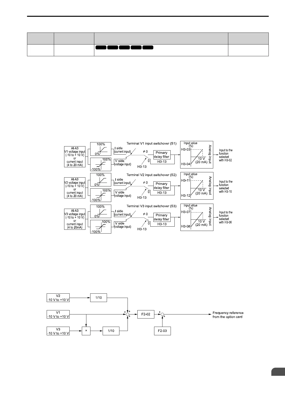
Figure 11.49 shows the individual input of analog inputs. H3-xx parameters set the function to input the analog
reference received from the AI-A3 card and to adjust the gain and bias of these signals.
Figure 11.49 Analog Input Reference Individual Input Block Diagram
1 : 3 Channels Added Together
Set b1-01 = 3 [Option PCB] to set addition input.
You can input the frequency reference directly. The sum value when you add the input from terminals V1 to V3
becomes the frequency reference.
Set F2-01 = 1 to use the AI-A3 card as addition input.
Figure 11.50 shows addition input. Use F2-02 [Analog Input Option Card Gain] and F2-03 [Analog Input Option
Card Bias] to adjust the analog reference gain and bias for addition input.
Figure 11.50 Analog Input Reference Addition Input Block Diagram
Use F2-02 and F2-03 to Adjust the Input Status
When the bias set in F2-03 is 0%, the gain in F2-02 and the addition input value set the ratio (%) of the maximum
output frequency output as the frequency reference.

 Loading...


