Parameter List
10
10.16 U: Monitors
YASKAWA SIEPC71061723A YASKAWA AC Drive CR700 Technical Manual 539
10.16 U: Monitors
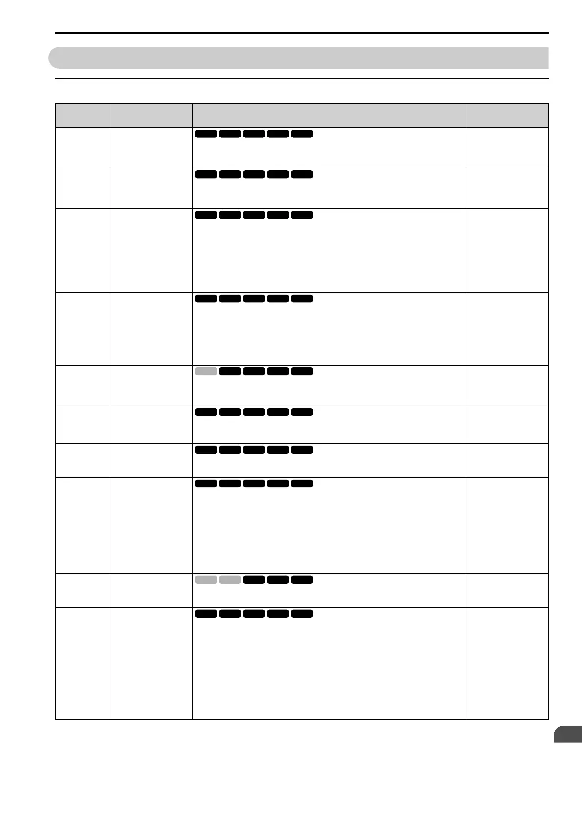
◆ U1: Operation Status Monitors
No.
(Hex.)
Name Description MFAO Signal Level
U1-01
(0040)
Frequency Reference
Shows the frequency reference value. Parameter o1-03 [Keypad Display Unit Selection] sets the
display units.
Unit: 0.01 Hz
10 V = Maximum
frequency (0 V to +10 V)
U1-02
(0041)
Output frequency
Shows the output frequency. Parameter o1-03 [Keypad Display Unit Selection] sets the display
units.
Unit: 0.01 Hz
10 V = Maximum
frequency (0 V to +10 V)
U1-03
(0042)
Output current
Displays the current output current.
The value of U1-03 appears in amperes (A) on the keypad. When viewing via MEMOBUS/
Modbus communications, the current is “8192 = drive rated current (A).” Current can be
calculated from the monitor value present at MEMOBUS/Modbus communications using
“Numerals being displayed / 8192 × drive rated current (A).”
Unit: Determined by the drive model.
• Models 2003 to 2033, 4002 to 4018: 0.01 A
• Models 2047 to 2415, 4024 to 4605: 0.1 A
10 V = Drive rated current
U1-04
(0043)
Control Method
Shows the drive control method.
0 : V/f Control
1 : V/f Control w/ PG
2 : Open Loop Vector
3 : Closed Loop Vector
4 : Advanced Open Loop Vector
No signal output available
U1-05
(0044)
Motor Speed
Shows the detected motor speed. Parameter o1-03 [Keypad Display Unit Selection] sets the
display units.
Unit: 0.01 Hz
10 V = Maximum
frequency (0 V to +10 V)
U1-06
(0045)
Output Voltage Ref
Shows the output voltage reference.
Unit: 0.1 V
200 V Class: 10 V = 200
Vrms
400 V Class: 10 V = 400
Vrms
U1-07
(0046)
DC Bus Voltage
Shows the DC bus voltage.
Unit: 1 V
200 V Class: 10 V = 400 V
400 V Class: 10 V = 800 V
U1-08
(0047)
Output Power
Shows the internally-calculated output power.
Changing the setting of A1-02 [Control Method Selection] changes the signal level of the analog
output.
• A1-02 = 0, 1 [V/f Control]: Drive capacity (kW)
• A1-02 = 2 to 4 [Vector Control]: Motor Rated Power (kW) [E2-11]
Unit: Display unit is determined by the maximum applicable motor output. The maximum
applicable motor output is determined by the drive capacity setting.
• Less than 11 kW (15 HP): 0.01 kW
• Less than 11 kW (15 HP): 0.1 kW
10 V: Drive capacity (motor
rated power) kW
(-10 V to +10 V)
U1-09
(0048)
Torque Reference
Shows the internal torque reference value.
Unit: 0.1%
10 V = Motor rated torque
(0 V to +10 V)
U1-10
(0049)
Input Terminal Status
Shows the status of the MFDI terminal where 1 = ON, 0 = OFF.
For example, U1-10 shows “00000011” when terminals S1 and S2 are ON.
bit0 : Terminal S1 (MFDI 1)
bit1 : Terminal S2 (MFDI 2)
bit2 : Terminal S3 (MFDI 3)
bit3 : Terminal S4 (MFDI 4)
bit4 : Terminal S5 (MFDI 5)
bit5 : Terminal S6 (MFDI 6)
bit6 : Terminal S7 (MFDI 7)
bit7 : Terminal S8 (MFDI 8)
No signal output available

 Loading...


