13.3 CPU Unit
13-10
13.3.2 Units and Circuit Boards in the CPU Unit
Control Circuit Board (JANCD-NCP01)
This board performs to control the entire system, display to the programming pendant, control
the operating keys, control operation, calculate motion type. This board has the Serial inter-
face for RS-232C, video output, PS2 connector, and LAN (100BASE-TX/10BASE-T). But this
board, however, cannot be used for video output and PS connector. (The video output and the
PS connector must be adjusted by the manufacturer only.)
Control Power Supply (CPS-420F)
This unit supplies the DC power (DC5V, DC24V, DC3.3V, DC±12V) for control (system, I/O,
brake). It is also equipped with the input function for turning the control power supply ON and
OFF.
Items Specifications
Input
Rating Input Voltage: 200/220VAC
Voltage Fluctuation Range: +10% to -15% (170 to 242VAC)
Frequency: 50/60Hz ± 2Hz (48 to 62Hz)
Output Voltage
DC + 5V : 20A
DC +24V : 12A (24V1: 4A, 24V2: 3.5A, 24V3: 4.5A)
DC +3.3V : 12A
DC +12V : 1.5A
DC -12V : 0.5A
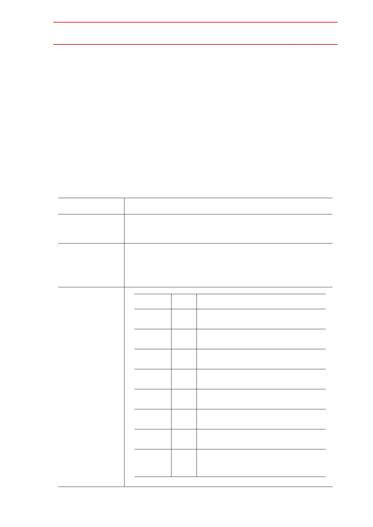
Indicator
DISPLAY Color Status
SOURCE Green Lights when AC power supply input
(Normally ON)
+5VSB Green Lights when +5V (internally used) is normal.
(Normally ON)
POWER
ON
Green Lights when DC power supply output
(Normally ON)
+5V Red Lights when +5V output error
(ON when abnormal)
+24V Red Lights when +24V output error
(ON when abnormal)
OTHER Red Lights when +3.3V,
±12V output error
(Lights if error occurs)
FAN Red Lights if a fan-related errors in the control
power supply unit. (Lights if error occurs)
OHT Red Lights when units interior overheats
(ON when abnormal)
Detection temperature: About 65
°C

 Loading...


