13.3 CPU Unit
13-27
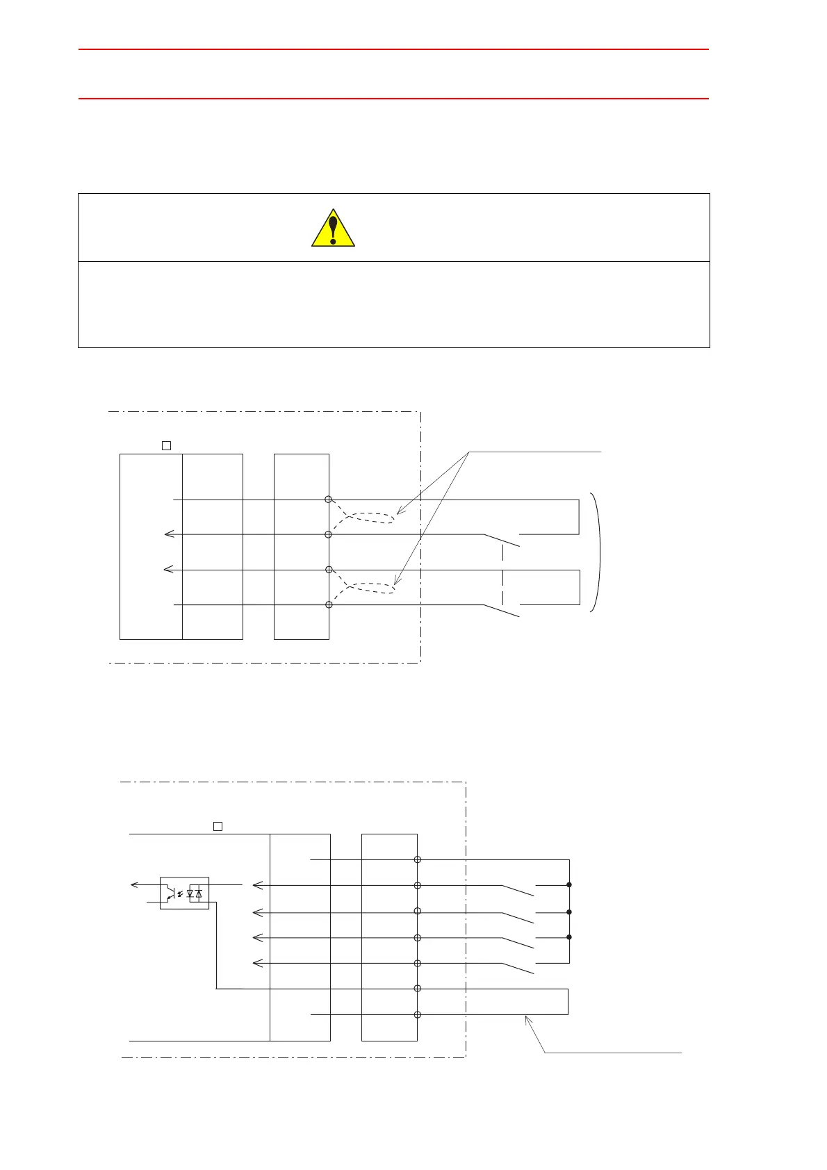
External Enable Switch
This signal is used to connect a Enable switch other than the one on the programming
pendant when two people are teaching.
Connection for External Enable Switch
Direct-in 1 to 4 (Option)
Connection for Direct-in 1 to 4
• Always connect the signals after removing jumper cable.
Injury or damage to machinery may result because the external emergency stop do not
work even if the signal is input.
CAUTION
+24V2
EXDSW1
NX100
Remove the jumper cable
EXDSW2
024V
External Enable Switch
-33
-34
-35
-36
Turned ON/OFF
at the same time
Robot system input
terminal block
MXT
JANCD-
NBB01
JANCD-
NIF01-
CPDIN1
024V
-8
-1
-2
-3
-4
-5
-7
NX100
CPDIN2
CPDIN3
CPDIN4
CPDINCOM
+24V2
Direct-in 1
Direct-in 2
Direct-in 3
Direct-in 4
Connect the jumper cable.
Robot system input
terminal block
MXT
JANCD-
NBB01
JANCD-
NIF01-

 Loading...


