8.4 ARM Control
8-37
8.4.3 Tool Load Information Setting
Tool Load Information
Tool load information includes weight, a center of gravity position, and moment of inertia at the
center of gravity of the tool installed at the flange. These are registered in the tool file.
How to Calculate Tool Load Information
Weight: W (Unit: kg)
The total weight of the installing tool is set.
It is not required to set a correct value, however, it is recommended to set a value slightly
larger than the actual load. (Round up the value with each fraction between 0.5 to 1 kg for
small and medium size manipulator, and 1 to 5 kgs for large manipulator.)
• Set the tool load information correctly.
The speed reducer longevity might decrease or the alarm might occur when the tool load
information is not set correctly.
• Confirm the operation path of robot of each job which uses the tool file
after the tool load information is changed.
Set the tool load information before teaching the job after the tool is installed.
Confirm the operation path of each job which uses the tool file when the tool load informa-
tion should be modified after teaching.
Modifying the tool load information may slightly change the operation path. To avoid injury
or damage to machinery caused by collision between tool and positioner, make sure to
check the operation path before executing a job.
CAUTION
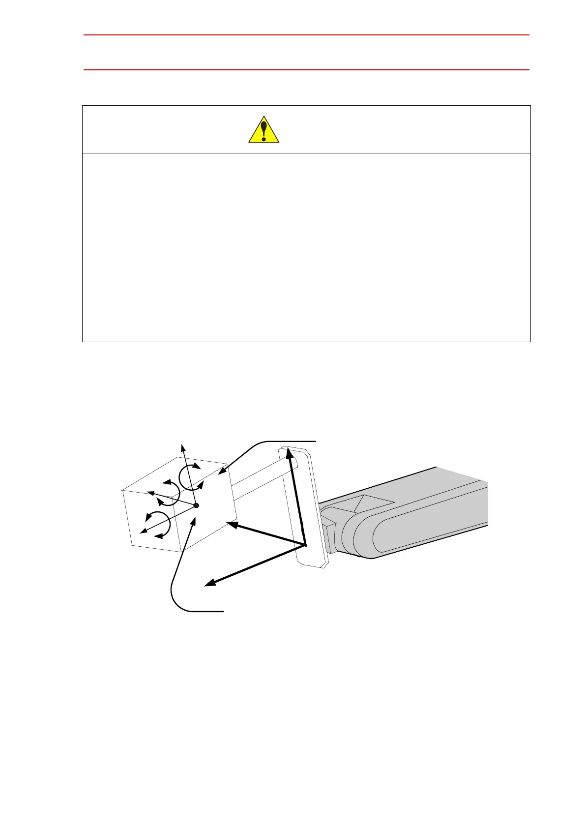
* Flange Coodinates
XF: It is a direction right above when T axis
is 0 pulse position and the flange surface
of the manipulator turned to the front.
YF: Y axis led by XF,ZF
ZF: Perpendicular direction from flange surface
XF
ZF
YF
XF'
ZF'
YF'
Center of Gravity Position
( Xg, Yg, Zg )
Iy
Iz
Ix
Moment of inertia around the Center of Gravity
Ix, Iy, Iz
Weight:W

 Loading...


