13.2 Power Supply Contactor Sequence Circuit Board (JANCD-NTU01-)
13-5
13.2 Power Supply Contactor Sequence Circuit Board
(JANCD-NTU01-)
The power supply contactor sequence circuit board is controlled by the major axes circuit
board (SGDR-AXA01A). The main functions of the contactor circuit board are as follows:
• Servo power supply contactor I/O circuit (dual circuit)
• Brake power supply output circuit
• Overrun signal input, tool shock sensor (SHOCK) signal input, and lamp power supply
output circuit to the manipulator
• External overrun signal input circuit (dual circuit)
• Servo-on enable signal input circuit (dual circuit)
• Fan alarm (optional) input circuit
• Fan control signal output circuit
• Contactor control signal output circuit (dual circuit)
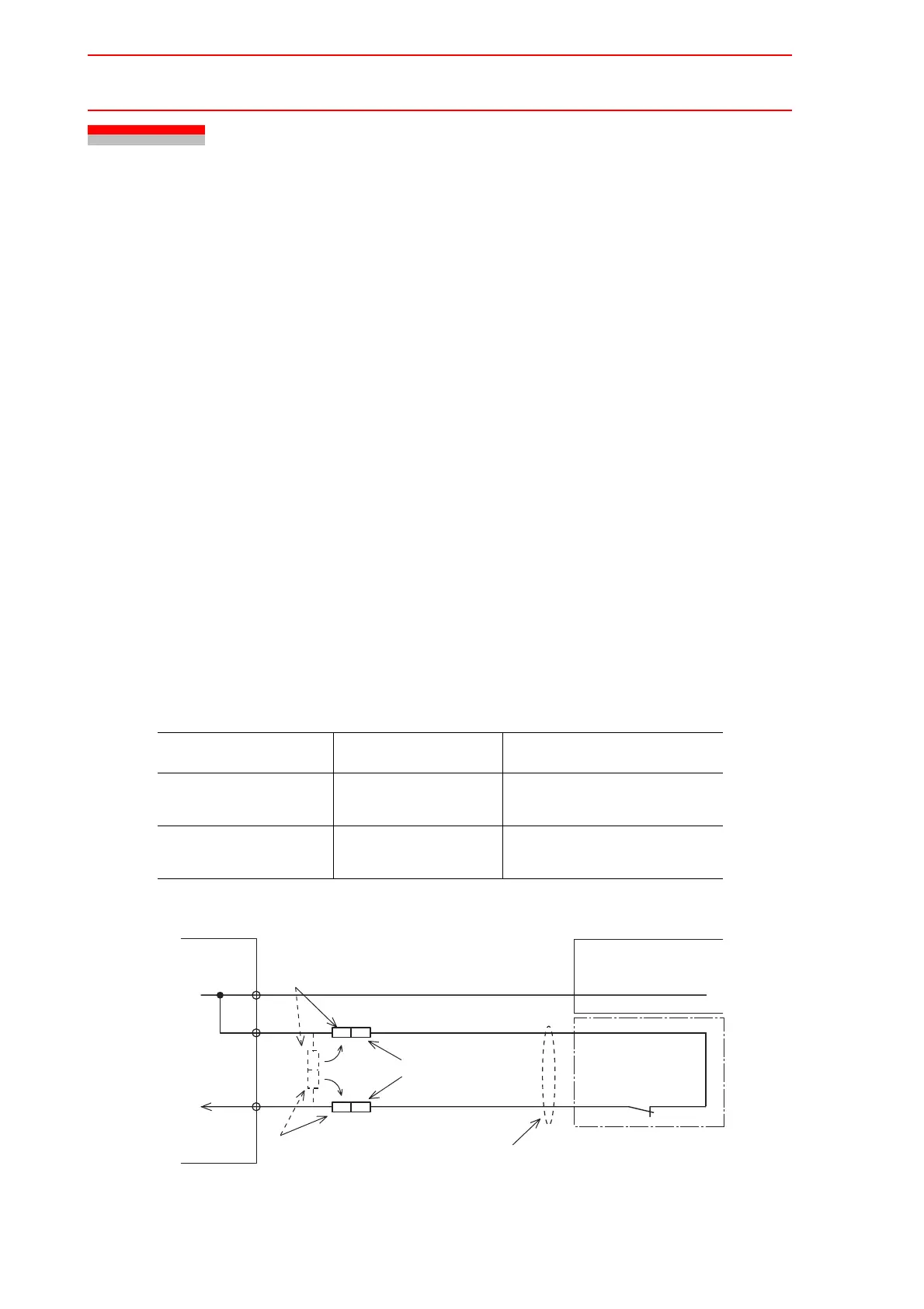
Connection for Tool Shock Sensor (SHOCK)
To connect the tool shock sensor directly to the tool shock sensor signal line
1. Disconnect the minus SHOCK (-) and 24VU pin terminal from the WAGO connector,
the NTU01-CN07 power supply contactor unit.
2. Connect the minus SHOCK (-) and 24VU pin terminals to the signal line of the tool
shock sensor. Use the following pin terminals for preparing the end of the signal line.
Fig. 1 Direct Connection to Tool Shock Sensor Signal Line
Pin Name Terminal Pin Terminal Model Signal Line Terminal Model
SHOCK- PC-2005W PC-2005M (manufactured by
NICHIFU Co., Ltd.)
24VU PC-2005M PC-2005W (manufactured by
NICHIFU Co., Ltd.)
+24V (manufactured by NICHIFU Co., Ltd.)
PC-2005M
Manipulator cable (signal)
SHOCK-
PC-2005W
(manufactured by NICHIFU Co., Ltd.)
Shock sensor
(Option)
CN07
-1
-3
-4
+24V2
SHOCK
Manipulator
PC2005W (manufactured
by NICHIFU Co., Ltd.)
Shock sensor signal cable
Power supply contactor unit
JZRCR-NTU
PC-2005M (manufactured by NICHIFU Co., Ltd.)
+24V
PC2005M (manufactured
by NICHIFU Co., Ltd.)

 Loading...


