13.2 Power Supply Contactor Sequence Circuit Board (JANCD-NTU01-)
13-6
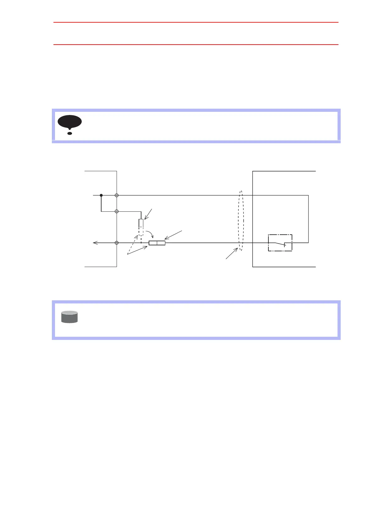
To connect the tool shock sensor with the cable that is built into the manipula-
tor
1. Disconnect the minus SHOCK (-) and 24VU pin terminal from the WAGO connector,
the NTU01-CN07 power supply contactor unit.
2. Connect the minus SHOCK (-) pin terminal to the minus SHOCK (-) pin terminal of the
manipulator.
Fig. 2 Connection with Manipulator Cable
Connection for External Axis Overrun (EXOT)
With a unit of standard specifications without an external axis, the external axis overrun input
signal is not used. In this case, a jumper cable is connected as shown in the following figure.
If an overrun input signal for an axis other than manipulator axes, for example the external
axis, is required, connect the signal input circuit in the following manner.
For safe reason, a dual circuits are used for the external axis overrun signal input. Connect
the external axis overrun signal so that both input signals are turned ON or OFF at the same
time. If only one signal is turned ON, an alarm occurs.
1. Remove the jumper cable between the connectors CN06-5 and -6 and between the
connectors CN06-7 and -8 of the JZRCR-NTU- power supply contactor unit.
2. Connect the external axis overrun wiring between the connectors CN06-5 and -6 and
between the connectors CN06-7 and -8 of the JZRCR-NTU- contactor unit.
Cable that is built into the manipulator is not connected to shocks sensor because the tool
shock sensor is a option. For connecting the tool shock sensor, refer to the wiring dia-
grams in the INSTRUCTIONS for the manipulator.
When the tool shock sensor input signal is used, the stopping method of the robot can be
specified. The stopping methods are hold stop and servo power supply OFF. Selection of
the stopping method is set in the display of the programing pendant. Refer to explanations
in " 8 System Setup " for details.
NOTE
+24V
PC-2005M
(manufactured by NICHIFU Co., Ltd.)
SHOCK-
PC2005M
(manufactured by
NICHIFU Co., Ltd.)
Supply cables (PG)
SHOCK-
PC-2005W
(manufactured by NICHIFU Co., Ltd.)
Shock sensor
(Option)
Use the manipulator cable
CN07
-1
-3
-4
+24V2
SHOCK
Manipulator
Power supply contactor unit
JZRCR-NTU
SUPPLE
-MENT

 Loading...


