11.2 Addition of Base and Station Axes
11-9
Connection Setting
In the CONNECT window, each axis in respective control groups is specified to be connected
to which connector of the SERVO board, or to which brake of the contactor unit, or to which
converter.
Operation Explanation
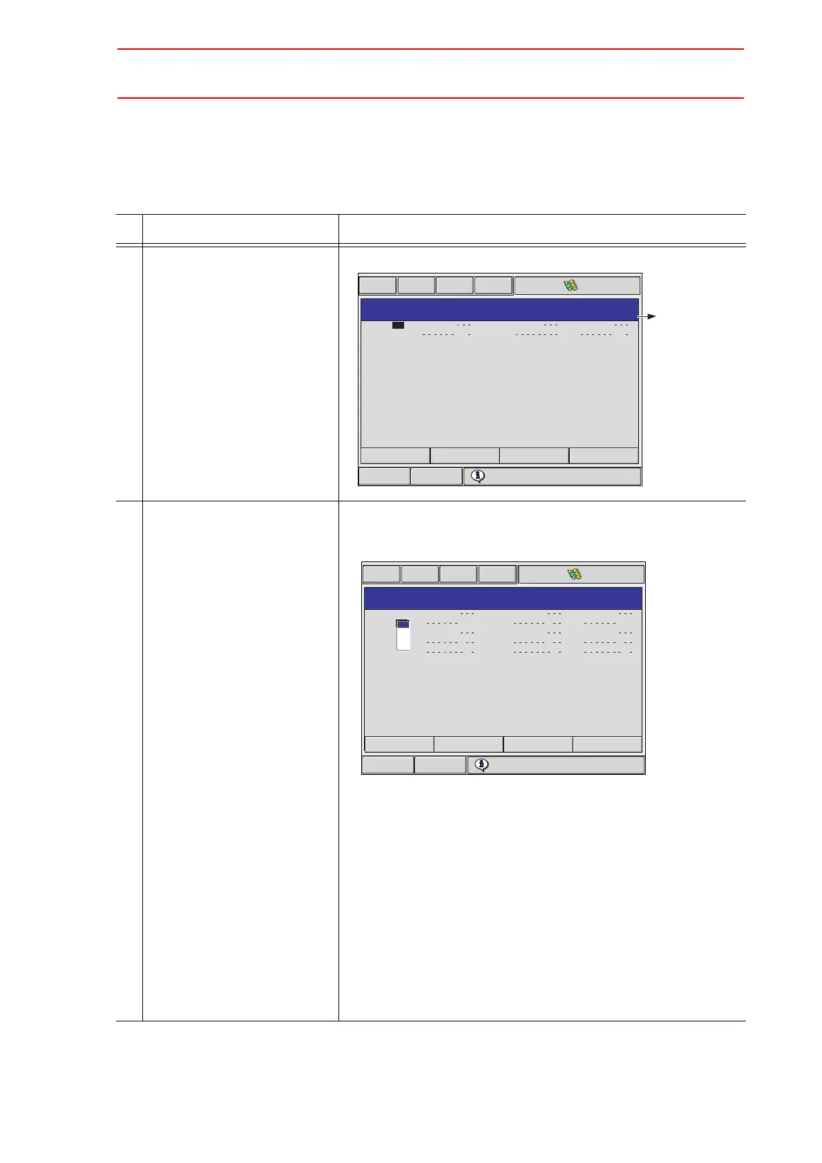
1 Confirm type of each control
group in the CONNECTION
window.
The connection status of each control group is displayed.
2 Select the connection item of
desired control group.
(Continued on the next page.)
The settable items are displayed.
When the item is selected, the window returns to the CONNEC-
TION window.
-It is possible to change the connection freely between each axis
of each control group and each connector (CN) of a SERVO
board. The number in [ ] represents the axis number, and it
indicates which axis is to be connected with which connector.
-It is possible to change the connection freely between each axis
of each control group and each brake (BRK) of a contactor unit.
The number in [ ] represents the axis number, and it indicates
which axis is to be connected with which brake.
-It is possible to change the connection freely between each axis
of each control group and each converter (CV). The number in
[ ] represents the converter number, and it indicates which axis is
to be connected with which converter.
Short CutMain Menu
CONNECT
: #1
: #1
R1
S1
SV CN<1 2 3 4 5 6 7 8 9> TU
BRK
<1 2 3 4 5 6 7 8 9> CN<1 2 3 4 5 6 7 8 9>
[
[
1 2 3 4 5 6
1 2
]
]
#1
#1
[
[
1 2 3 4 5 6
2
]
]
CV
CV
[
[
1 1 1 1 1 1
1 1
]
]
Choose the number of servo board which connec
Control group which
is set as "NONE" in
the
CONTROL GROUP
window is not shown.
Short CutMain Menu
CONNECT
: #1
: #1
: #2
: #2
: #2
R1
B1
R2
S1
S2
SV CN<1 2 3 4 5 6 7 8 9> TU
BRK
<1 2 3 4 5 6 7 8 9> CN<1 2 3 4 5 6 7 8 9>
[
[
[
[
[
1 2 3 4 5 6
1 2 3 4 5 6
1 2 3
]
]
]
]
]
1
1
#1
#1
#1
#1
#1
[
[
[
[
[
1 2 3 4 5 6
1 2 3 4 5 6
3
]
]
]
]
]
1
1
CV
CV
CV
CV
CV
[
[
[
[
[
1 1 1 1 1 1
1 1 1 1 1 1
1 1 1
]
]
]
]
]
2
3
Choose the number of servo board which connects
#1
#2
#3
#4

 Loading...


