NoteAction
2 pcs, M6 x 16.Fit the attachment plate to the base of the
robot with the two attachment screws.
7
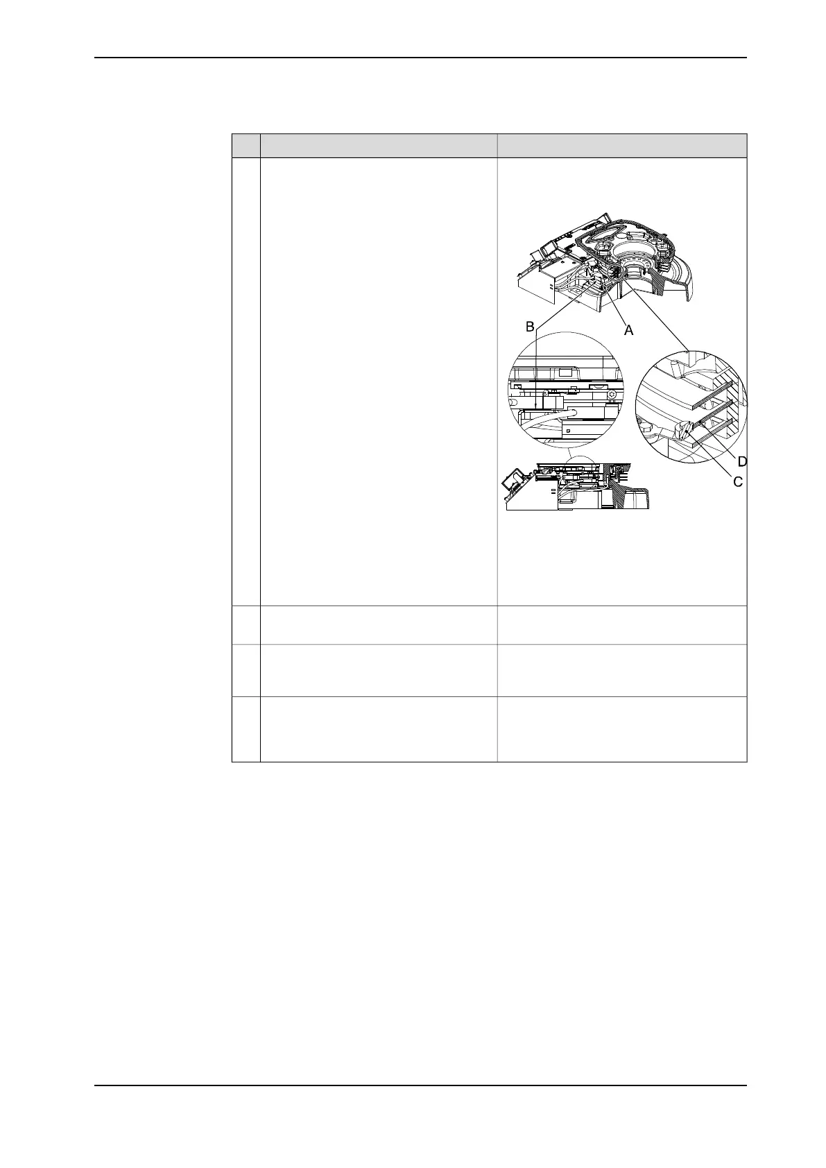
Shown in the figure Location of position
switch, axis 1 on page 113.
xx0400001358
A Attachment plate
B Shims
C Roller
D Cam
Fit the switches to the attachment plate.
Adjust the height of the switches with
shims until each roller aligns with corres-
ponding cam.
Shown in the figure Location of position
switch, axis 1 on page 113.
Secure the cabling inside the housing
with cable straps.
8
The cabling and connection points are
specified in section Position switch cables,
robot base to controller (option) on page 121.
Connect the position switch cabling.9
The system parameters that must be
changed (Upper joint bound and Lower joint
bound) are described in Technical reference
manual - System parameters.
Adjust the software working range limita-
tions (system parameter configuration)
to correspond to the mechanical limita-
tions.
10
Product manual - IRB 1600/1660 115
3HAC026660-001 Revision: W
© Copyright 2006-2018 ABB. All rights reserved.
2 Installation and commissioning
2.4.5 Installation of position switch, axis 1
Continued