6.
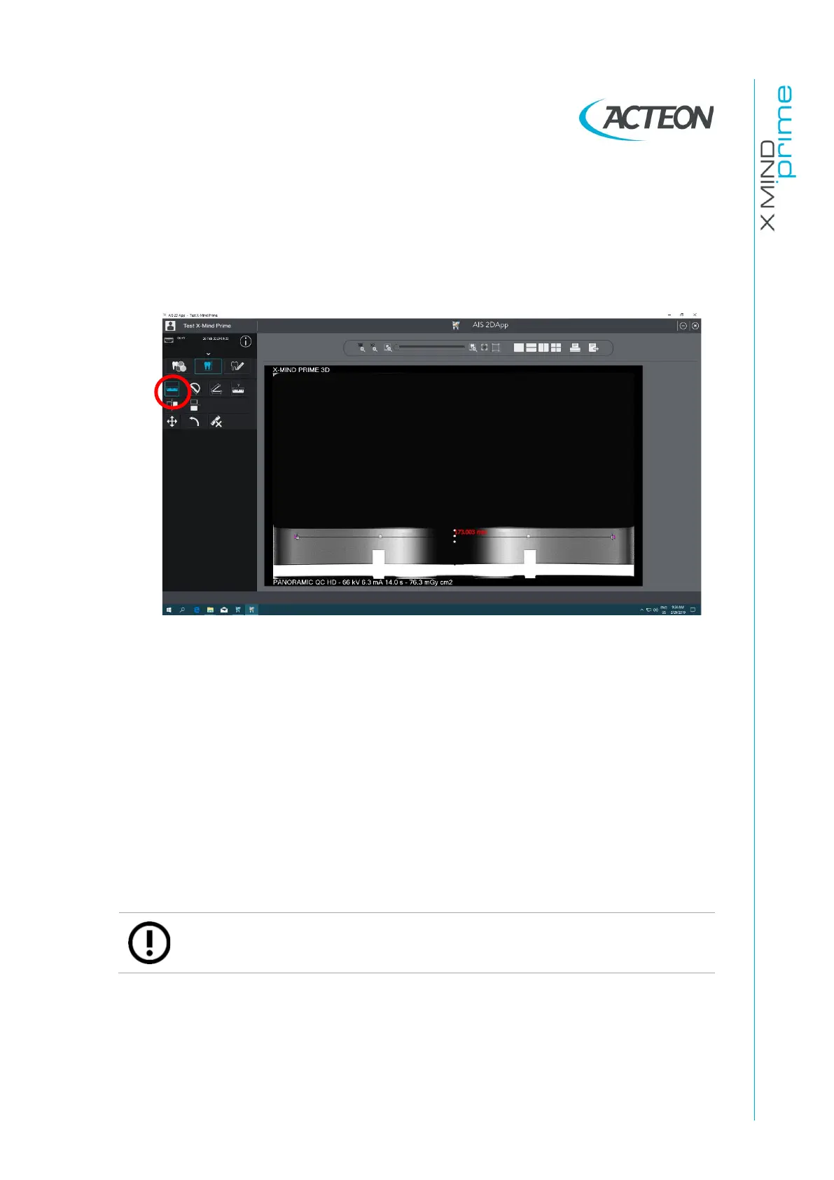
Select “Panoramic QC” exam clicking on the left area of the virtual interface.
7.
Make an exposure at 66kV, 6.3mA (see User’s Manual – chapter 9).
8.
Select the “Ruler” icon and measure the distance between the two external
spheres; this value must be 170mm ± 2mm.
9.
If distance is outside the tolerance range, open “PhD_C_Test.exe” and adjust
the Y axis offset (see paragraph 8.4) accordingly. Repeat the exposure.
10.
Measure also the two halves of the image in order to check symmetry. The
difference has to be max. 2mm.
11.
If distance is outside the tolerance range, perform the following test:
•
Visually check that the rotation offset is properly configured. This can be
done by checking the laser alignment with the support plate as described
in the User Manual, paragraph “Laser Alignment check”
•
If the rotation offset is correct, open “PhD_C_Test.exe” and adjust the chin
rest offset (see paragraph 8.4).
Repeat the exposure.
Note
If the legislation in your country requires a white border around the image,
you can change the collimator offsets (see paragraph 11.2.9).



 To Next Page