4.2
Block diagram
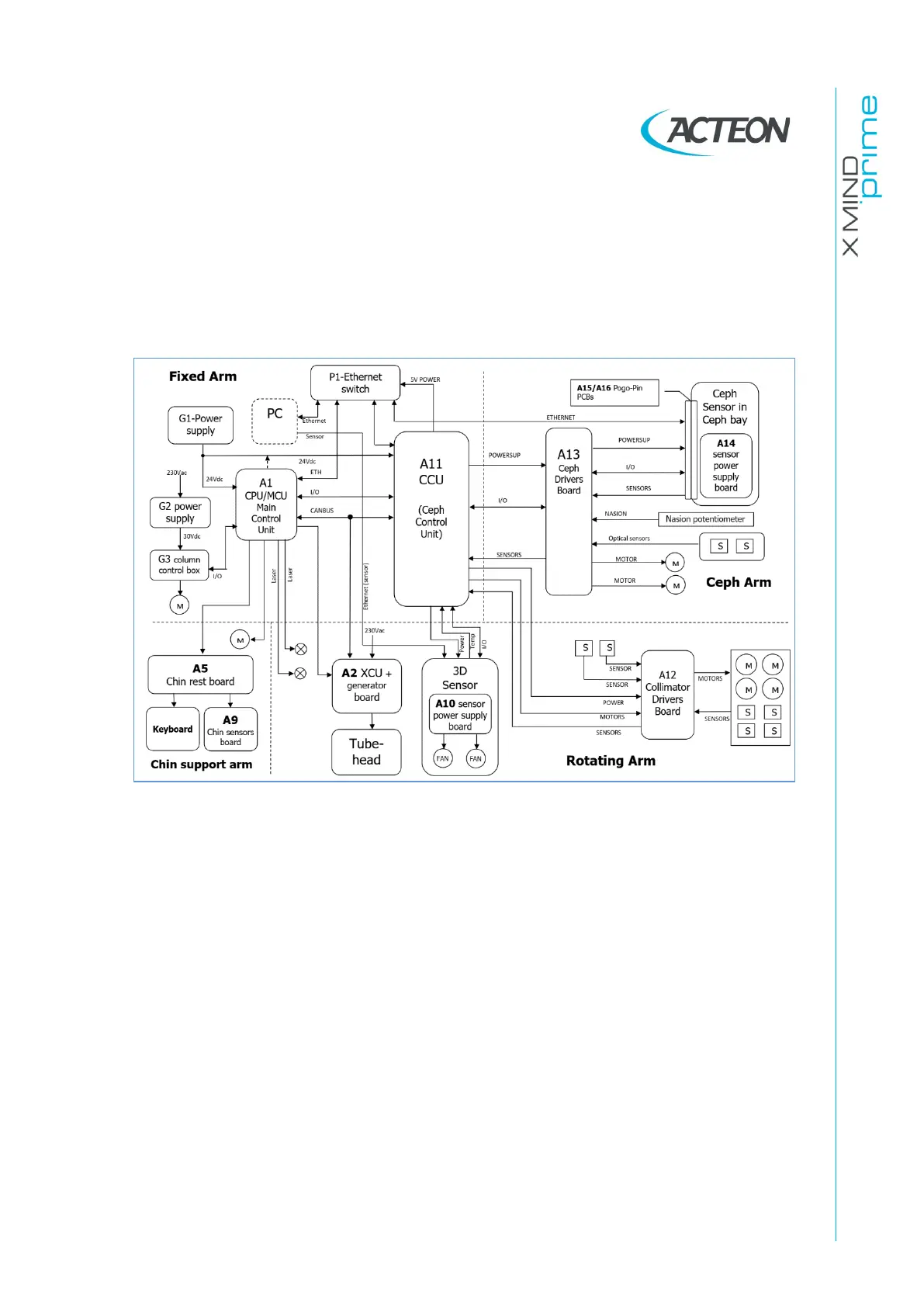
This paragraph provides a brief description, at block diagram level, of the X-MIND
prime 3D. Aim of this paragraph is to provide a brief description of the system. More
details about the electronic circuits which compose the system can be obtained by
analyzing the schematics provided in chapter 12.
MCU board A1 is the main board that manages directly all the components of the
unit.
It is connected to the following components:
•
Power supply assembly (G1)
•
Chin Rest motor
•
Zero position sensors
•
X-ray button
•
External signal board (A8)
•
Lift motors control box (G3)
•
Generator board XCU (A2) ---> (Tubehead)
•
Ceph Control Board (CCU, A11)
•
Collimator driver board (A12)
•
Ceph Driver board (A13)
•
Ceph Sensor power supply board (A14)
•
Overlay keyboard
•
3D sensor Power board (A10)
•
3D Sensor ---> (PC) Ethernet 1
•
Ceph sensor and host PC via a 5-ports ethernet switch