Service Manual – Corrective maintenance
SERVICE MANUAL • X-MIND prime 3D • (19) • 11/2019 • NXMPEN080A
3.
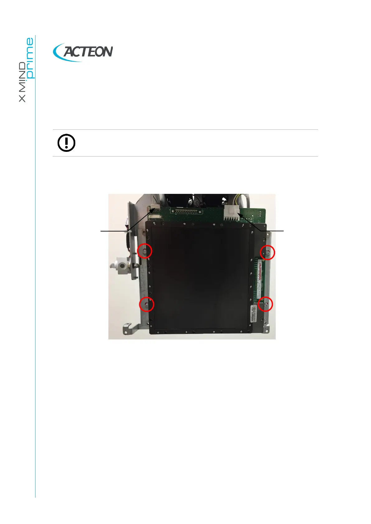
First operator holds the sensor with both hands while the second operator
unscrews the 4 screws indicated by the red circles in the image:
Figure 51
4.
Second operator removes the Ethernet cable.
5.
Place the defective sensor in the box of the spare sensor, following the
packaging instructions supplied with the new 3D sensor.
6.
Connect the Ethernet cable to the new sensor. Place the sensor on the unit and
tighten the four screws removed before. Connect the J15 and J99 cables.
7.
Verify the X-ray beam alignment (see paragraph 11.2.9.1).
8.
Perform sensor calibration (see paragraph 10.2).
9.
Verify the 3D lateral offset (see paragraph 11.2.10).
 Loading...