Troubleshooting Switch Modules
OPPM
Please follow the troubleshooting steps in based upon the states of the LEDs.
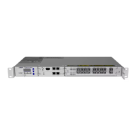
The OPPMhas five LEDs on the faceplate:
• “P” to indicate the power supply status
• “Mod” to indicate the operation status of the module
• "C" to indicate the client interface status
• “NW” and “NE” to indicate the network interface status
Note
Before you start with troubleshooting, ensure that the current firmware package is installed on
the OPPMmodule. For details on updating module firmware, refer to “Updating the NE Software
Release” on p.617 and “Performing Other Software Update Actions” on p.628.
Note
Before you start with troubleshooting, ensure that the administrative state of the affected module
is set to “Maintenance”.
Note
If your module has an LED status that is not represented in Table 74, please contact your ADVA
Optical Networking Technical Services Representative.
LED Names Colors Potential Cause Solution for Troubleshooting
All LEDs Red Initialization error 1 Remove the module, wait 10 seconds, then
insert the module into the slot.
2 If the indication persists, return the module.
P Off Power source is
missing, disabled or
failed
1 Ensure the module is properly inserted in the
slot.
2 Check PSU "P" LED.
o
If the LED is off, refer to “Troubleshooting
Power Supply Units” on p.88.
o
If the LED is green, return the module.
Internal power failure 1 Remove the module, wait 10 seconds, then
insert the module into the slot.
2 If the indication persists, return the module.
Yellow Power is abnormal 1 Remove the module, wait 10 seconds, then
insert the module into the slot.
2 If the indication persists, return the module.
Table 74: LED Status of the OPPM
FSP 3000R7 Maintenance and Troubleshooting Manual - Product Release 16.2 - Document Issue A 415