7-26 Chapter 7
Source Troubleshooting
Phase Lock Error
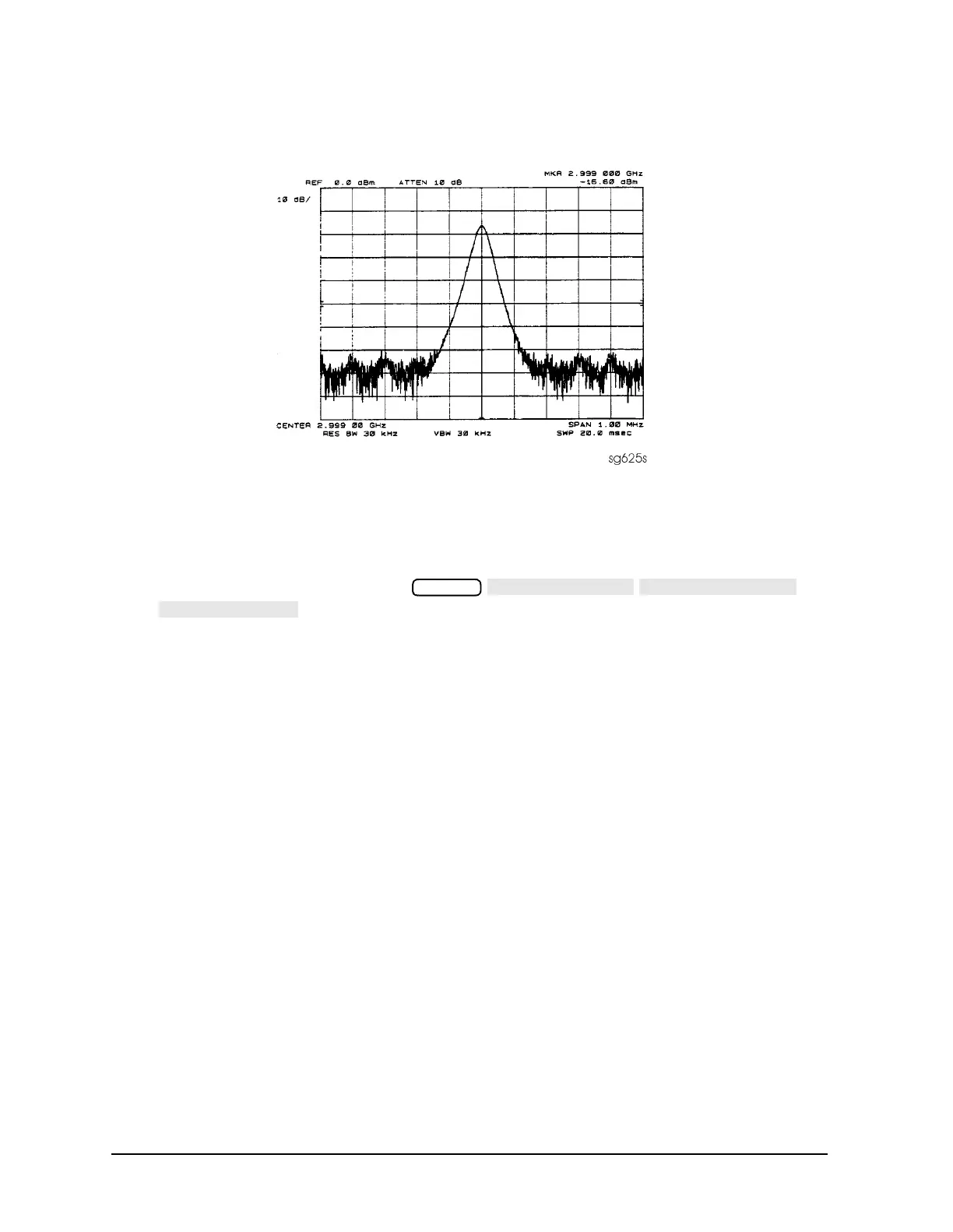
Figure 7-24 High Quality Comb Tooth at 3 GHz
3. If the signal at the A7 output is good, check the A7-to-A4 cable.
4. If the signal is not as clean as Figure 7-24, observe the HI OUT input signal to the
A7 assembly.
a. On the network analyzer, press
. Otherwise do not readjust the instrument. Remove the A14-to-A7
SMB cable (W9) from the A7 pulse generator assembly (CW ≈ 16 MHz).
b. Set the spectrum analyzer to a center frequency of 45 MHz and a span of 30 MHz.
Connect it to the A14-to-A7 cable still attached to the A14 assembly. Narrow the
span and bandwidth to observe the signal closely.
5. If the HI OUT signal is as clean as Figure 7-25, the A7 assembly is faulty.
Otherwise, check the A14-to-A7 cable or recheck the A13/A14 fractional-N as described
ahead.
Rechecking the A13/A14 Fractional-N
Some phase lock problems may result from phase noise problems in the fractional-N loop.
To troubleshoot this unusual failure mode, do the following:
1. Set the network analyzer at 60 MHz in the FRACN TUNE mode.
2. Use a spectrum analyzer, to examine the HI OUT signal from the A14 assembly. The
signal should appear as clean as Figure 7-25. The comb shape may vary from pulse
generator to pulse generator.
System

 Loading...


