Chapter 7 7-29
Source Troubleshooting
Phase Lock Error
Phase Lock Check by Signal Examination
To confirm that the A11 assembly is receiving the signals required for its proper operation,
perform the following steps.
1. Place the A11 assembly on the large extender board.
2. Switch on the analyzer and press .
3. Check for the signals listed in Table 7-8.
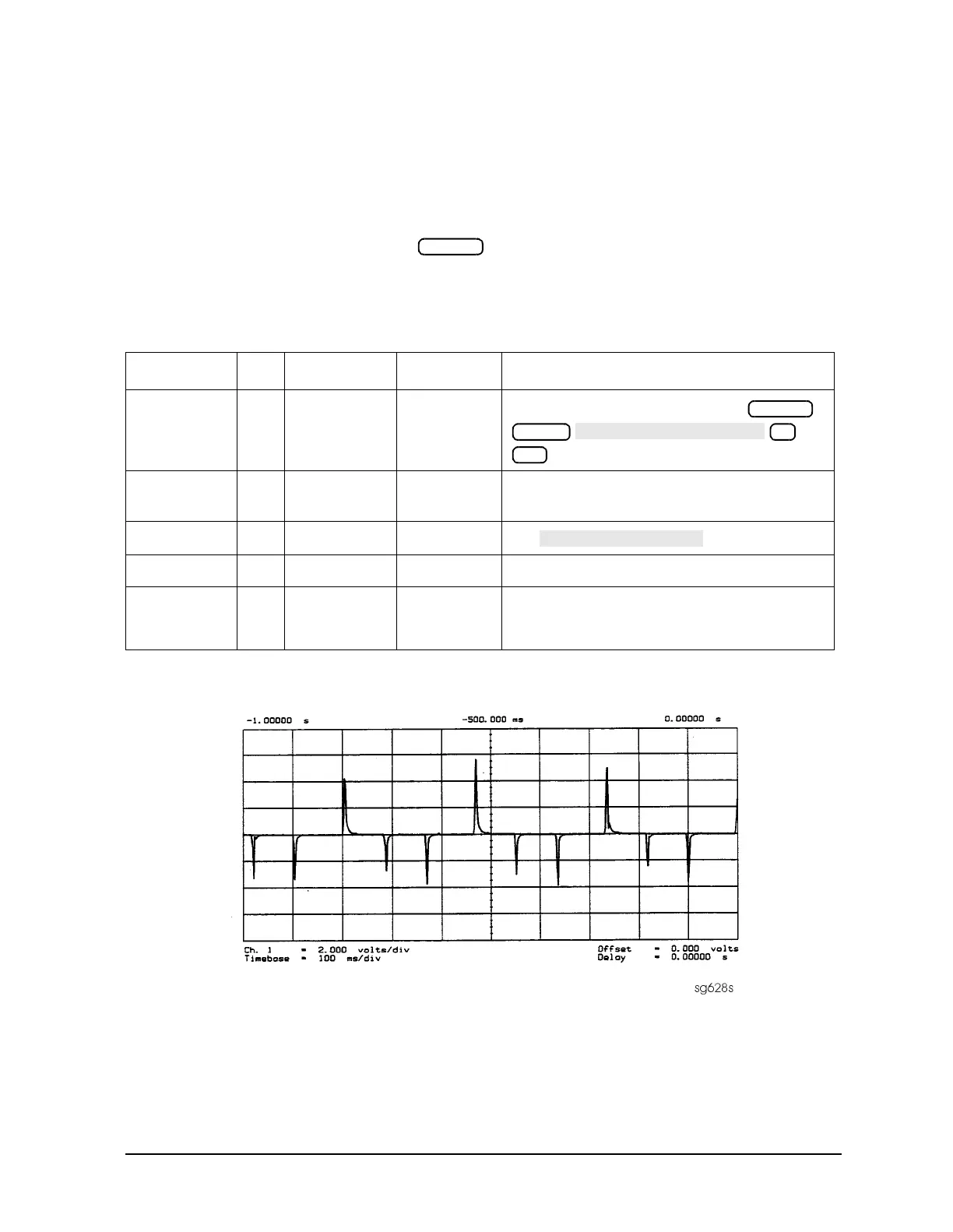
Figure 7-27 FM Coil – Plot with 3 Point Sweep
4. If any of the input signal is not proper, refer to the overall block diagram in
Chapter 4 as an aid to troubleshooting the problem to its source.
5. If any of the output signals is not proper, the A11 assembly is faulty.
Table 7-8 A11 Input Signals
Mnemonic I/O Access See Figure Notes
FM COIL − O A11P1-3,33
Figure 7-27
Aids YO COIL in setting YIG. Press
to observe this signal.
REF I A11TP9
Figure 7-9,
Figure 7-10
Observe both low band and high band CW
frequencies.
YO COIL + O A11P1-2,32
Figure 7-7
Use .
YO COIL − O A11P1-1,31
Figure 7-7
1ST IF I A11 PL IF IN
Figure 7-26
Check for 1 MHz with tee a A11 jack (not at
cable end) in high band. Use A7 pulse generator
check setup.
Preset
Preset
Menu
3
x1

 Loading...


