10-22 Chapter 10
Service Key Menus and Error Messages
Service Key Menus
Analog Bus Nodes
The following paragraphs describe the 31 analog bus nodes. The nodes are listed in
numerical order and are grouped by assembly. Refer to the “Overall Block Diagram” in
Chapter 4 , “Start Troubleshooting Here” for node locations.
A3 Source To observe six of the eight A3 analog bus nodes (not node 5 or 8), perform step
A3 to set up a power sweep on the analog bus. Then follow the node specific instructions.
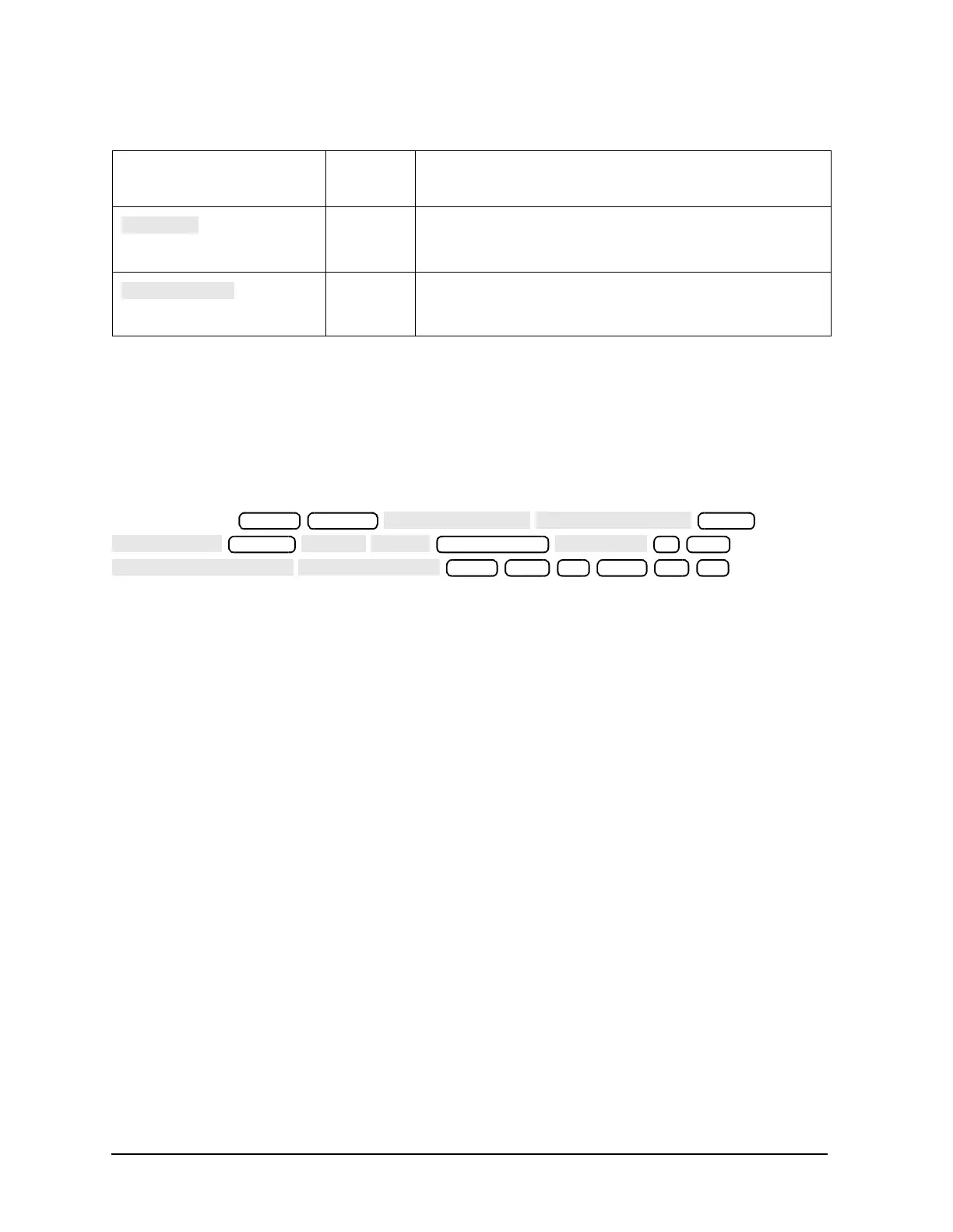
Step A3: Press
.
N/A Switches the counter to monitor the A14 fractional-N VCO
frequency at the node shown on the “Overall Block Diagram,”
in
Chapter 4 , “Start Troubleshooting Here.”
N/A Switches the counter to monitor the A14 fractional-N VCO
frequency after it has been divided down to 100 kHz for phase
locking the VCO.
Table 10-12 Analog In Menu Keys
Key GPIB
Mnemonic
Description
Preset System
Meas
Format
Sweep Setup
3 G/n
Start −15 x1 Stop 10 x1
 Loading...


