Chapter 10 10-35
Service Key Menus and Error Messages
Service Key Menus
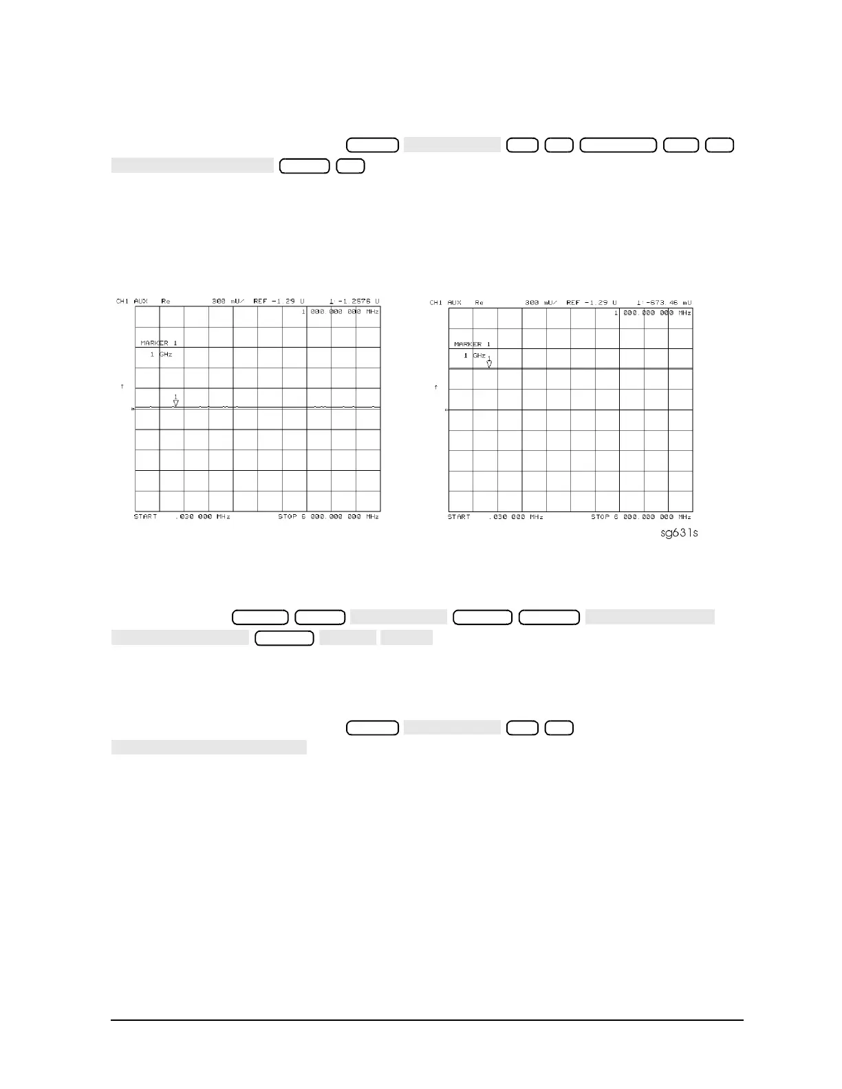
Node 20 IF Det 1 (IF after 30 MHz filter)
Perform step A11 and then press
.
The trace should be a flat line across the entire frequency band at least 0.5 V greater than
Vbb (node 14). The correct trace indicates the presence of IF after the first 30 MHz
filter/limiter.
Figure 10-14 Analog Bus Node 20
A12 Reference To observe the A12 analog bus nodes perform step A12, below. Then
follow the node-specific instructions.
Step A12: Press
.
Node 21 100 kHz (100 kHz reference frequency)
Perform step A12 and then press
. This node counts the A12 100 kHz reference signal that is
used on A13 (the fractional-N analog assembly) as a reference frequency for the phase
detector.
Node 22 A12 Gnd 1 (ground)
20 x1 Scale Ref 0.3 x1
−1.29 x1
Preset Meas
Marker System
Format
21 x1

 Loading...


