10-36 Chapter 10
Service Key Menus and Error Messages
Service Key Menus
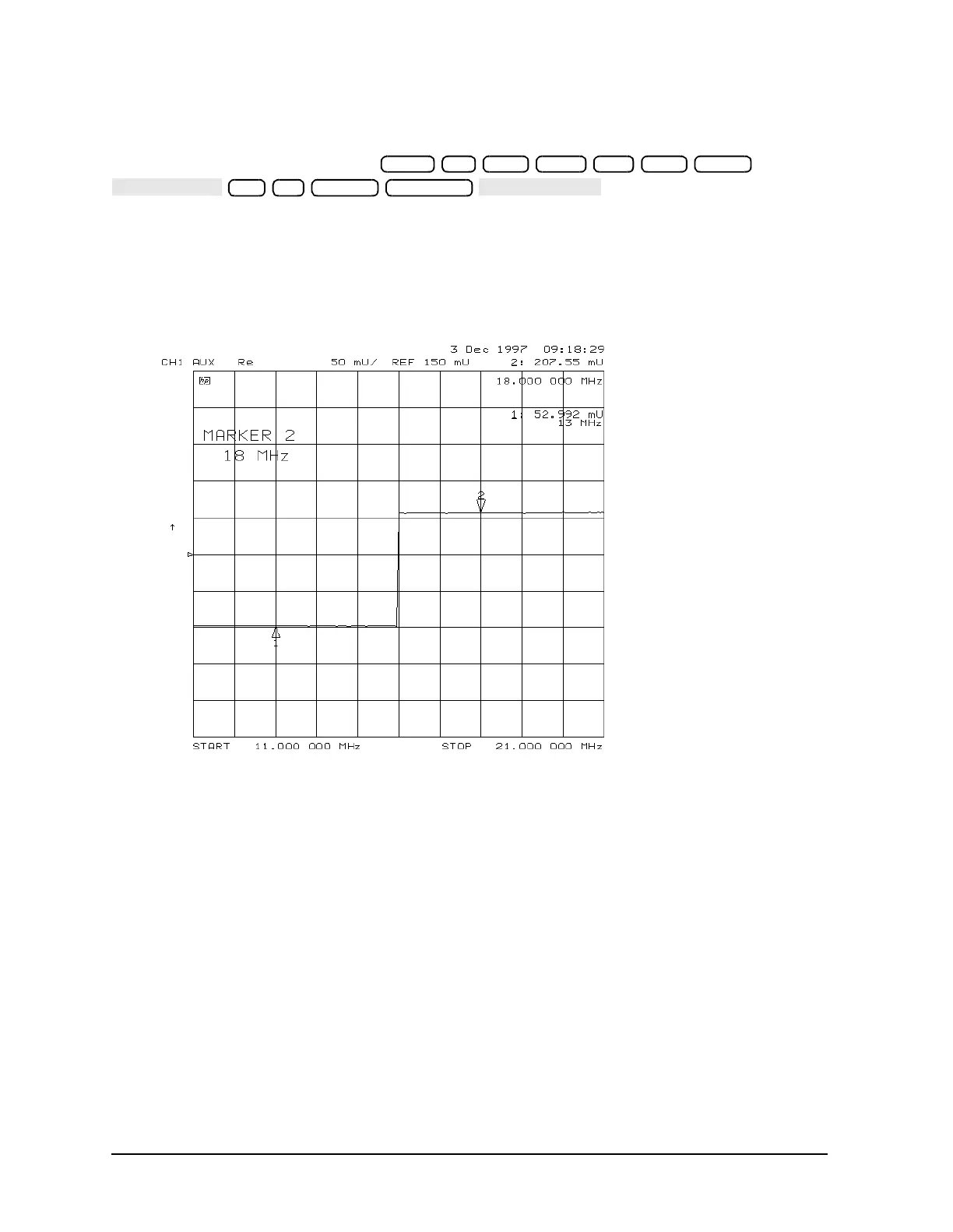
Node 23 VCO Tune (A12 VCO tuning voltage)
Perform Step A12 and then press
.
The trace should show a voltage step as shown in Figure 10-15. At normal operation, the
left half trace should be 0 ±1000 mV and the right half trace should be 100 to 200 mV
higher (that is, one to two divisions). If the trace does not appear as shown in Figure 10-15,
refer to “High/Low Band Transition Adjustment” on page 3-47.
Figure 10-15 Analog Bus Node 23
Start
M/µ Stop 21 M/µ Meas
23 x1 Marker Scale Ref

 Loading...


