Chapter 16 485
W-CDMA Uplink Digital Modulation for Receiver Test
Setting Up a Multiple PRACH Signal
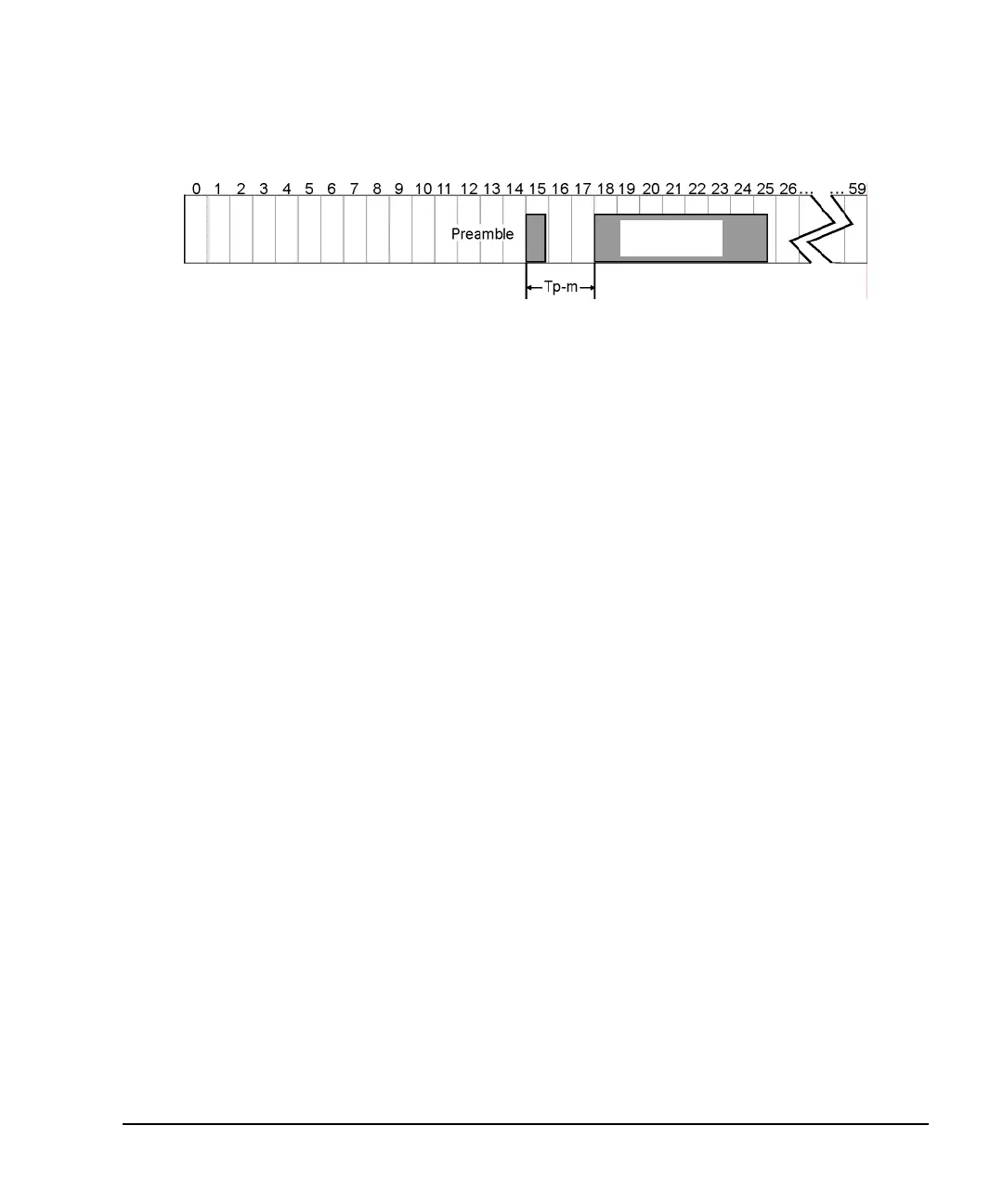
Figure 16-28 Tp-m Setting
a. Highlight the Tp-m (time from the preamble to the message part) field.
b. Press
4 > Enter.
The range for this field is 1 to 15.
You have now increased the distance from the for the Tp-m from three access slots (3.99 ms) to four
(5.32 ms). An access slot is 1.33 ms in length.
If you need to have a UE repeat its PRACH multiple times within the 80 ms time period, you may want
to keep the Tp-m to a minimum value. Since you are limited to 60 access slots (80 ms), an increase in the
Tp-m value further limits the number of times a UE’s PRACH can be repeated.
4. Press
Apply Channel Setup.
When the Apply Needed annunciator appears, press the
Apply Channel Setup softkey. You will not see a
change in the signal until you press this softkey.
Setting the Control Part Parameters
1. Select the message part control data.
a. Highlight the Msg-Ctrl Data field.
b. Press
Edit Item.
Notice that you have a selection of different control information types with the factory default being
3GPP STD (pilot bit pattern as stated in the 3G TS 25.211 V3.3.0 (2002-03). You can select a PN
sequence, FIX 4 pattern, or create your own control pilot information with the
User File selection.
c. Ensure that
3GPP STD is highlighted and press Return.
2. Set the TFCI (transport format combination indicator) bits.
a. Highlight the TFCI Pattern field.
b. Press
Edit Item.
Notice that you have a selection of different TFCI patterns that you can choose from, including the
ability to create your own pattern (
User File softkey). The base station uses the TFCI to determine
what transport channel configuration is being used. The TFCI pattern, relative to a transport channel
Message Part
10 ms TTI