Electrical
Electrical Overview
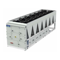
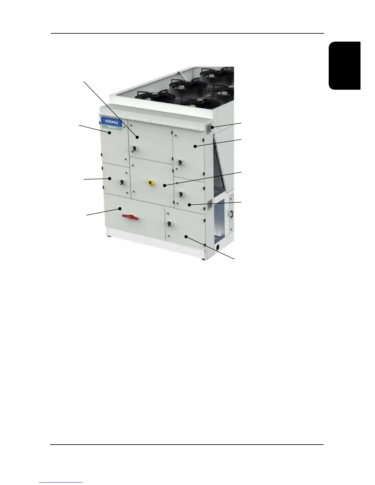
Location of Electrical components within the chiller.
A weatherproof electrical power and controls panel shall be situated at the end of the unit and contains:
● Individual mains power isolation for each circuits compressors.
● Separate electrical isolation for fans.
● Dedicated bus-bar chamber for connection of incoming 3 phase and earth mains power supply.
● Emergency stop tted to controls compartment door.
● Separate, fully accessible controls compartment allowing adjustment of set points whilst the unit is operational.
● Circuit breakers for protection of all major unit components.
● Phase rotation relay incorporating phase loss protection.
● The electrical power and control panel is wired to the latest European standards and codes of practice.
● Mains supply is 3 phase and a neutral is not required, refer to interconnecting wiring.
● Separate 230V 1ph 50Hz permanent supply is required for the controls and safety features. Isolator allows for a
maximum cable size of 10 mm.
● Electrical terminals for external evaporator pipe work trace heating (230V / 500 Watt) are provided. The external
trace heating is tted by others.
Pumps
Circuit 3
Compressors
Bus-bar Chamber
Fans